 |

|
(b) For establishments not listed in Table I, contact the Division of Environmental Public Health of the department for assistance with determining flows.
(c) Designs for flows less than estimated from Table I may be considered based on substantial evidence (such as water meter readings) that lower flows will occur. Flow data from similar installations of equal capacity and similar surroundings may be considered on an individual basis.
(Indiana State Department of Health;
Authority: |
|||||||||||||||||||||||||||||||||||||||||||||||||||||||||||||||||||||||||||||||||||||||||||||||||||||||||||||||||||||||||||||||||||||||||||||||||||||||||||||||||||||||||||||||||||||||||||||||||||||||||||||||||||||||||||||||||||||||||||||||||||||||||||||||||||||||||||||||||||||||||||||||||||||||||||||||||||||||||||||||||||||||||||||||||||||||||||||||||||||||||||||||||||||||||||||||||||||||||||||||||||||||||||||||||||||||||||||||||||||||||||||||||||||||||||||||||||||||||||||||||||||||||||||||||||||||||||||||||||||||||||||||||||||||||||||||||||||||||||||||||||||||||||||||||||||||||||||||||||||||||||||||||||||||||||||||||||||||||||||||||||||||||||||||||||||||||||||||||||||||||||||||||||||||||||||||||||||||||||||||||||||||||||||||||||||||||||||||||||||||||||||||||||||||||||||||||||||||||||||||||||||||||||||||||||||||||||||||||||||||||||||||||||||||||||||||||||||||||||||||||||||||||||||||||||||||||||||||||||||||||||||||||||||||||||||||||||||||||||||||||||||||||||||||||||||||||||||||||||||||
| Table II – Minimum Separation Distances | ||
| Minimum Distance in Feet from | Septic Tank and Other Treatment Units, Dosing Tank, Lift Station | Soil Absorption System |
| Private water supply well1,2 | 100 | 100 |
| Private geothermal well1,2 | 100 | 100 |
| Commercial water supply well1 | 100 | 100 |
| Commercial geothermal well1 | 100 | 100 |
| Public water supply well, lake,1,3 or reservoir1,3 | 200 | 200 |
| Other pond, retention pond, lake, or reservoir3 | 50 | 50 |
| Storm water detention area3, 4 | 25 | 25 |
| River, stream, ditch, or drainage tile5 | 25 | 25 |
| Buildings, foundations, slabs, garages, patios, barns, aboveground and belowground swimming pools, retaining walls, closed loop geothermal systems, roads, driveways, parking areas, or paved sidewalks | 106 | 107 |
| Front, side, or rear lot lines | 5 | 5 |
| Water lines continually under pressure | 10 | 10 |
| Suction water lines | 50 | 50 |
| 1The distances enumerated shall be doubled for soil absorption systems constructed where there exist horizons, layers, or strata within thirty-four (34) inches of the ground surface with a soil loading rate greater than seventy-five hundredths (0.75) gallons per day per square foot as determined from Table V of section 78(b)(8) of this rule, unless that hazard can be overcome through on-site sewage system design. | ||
| 2The separation distance to a private water supply well abandoned in accordance with |
||
| 3Measured from the normal or ordinary high water mark. | ||
| 4Storm water detention area: area designated for the temporary detention of storm water, with the outlet located at the lowest elevation of the depression. | ||
| 5See section 63(f) of this rule for subsurface drainage system separation. | ||
| 6Patios without footers, aboveground swimming pools, and sidewalks may be located within ten (10) feet of septic tank, as long as no required access points are obstructed. | ||
| 7A minimum separation of ten (10) feet is required on all sites. | ||
(b) Sewers shall not be located within one hundred (100) feet of any water supply well or subsurface pump suction line, except as follows:
(1) Sewers constructed of waterworks grade ductile iron pipe with tyton or mechanical joints, or PVC pressure sewer pipe with an SDR rating of twenty-six (26) or less with compression gasket joints, may be located within the one hundred (100) foot distance.
(2) In no case shall sewers be located closer than thirty (30) feet to any water source.
(c) If it is necessary to locate sewers or drains closer than two hundred (200) feet to a well or pump suction line in a mobile home park with twenty-five (25) or more lots, waterworks grade ductile iron pipe with mechanical joints, or SDR 26 PVC pressure sewer pipe with compression fittings shall be used. The piping shall not be constructed closer than seventy (70) feet to water sources.
(d) Water lines and sewers shall not be laid in the same trench and shall have the following requirements:
(Indiana State Department of Health;
(1) A horizontal separation of ten (10) feet shall be maintained between water lines and sewers.
(2) Where crossings are necessary, a minimum of eighteen (18) inches vertical clearance must be maintained with the water line positioned above the sewer line when possible.
(3) When it is impossible to maintain proper horizontal and vertical separation, the sewer shall be constructed of ductile iron pipe with mechanical joints or PVC pressure sewer pipe with an SDR rating of twenty-six (26) or less, having mechanical or compression gasket joints within ten (10) feet of the water line with the water line positioned above the sewer line when possible. The sewer shall be pressure tested to assure watertightness prior to back filling.
410 IAC 6-10.1-62 Dispersal area
Authority: Affected: IC 16-19-3-4
Sec. 62. (a) A dispersal area is required for a soil absorption system when:
(1) the soil loading rate used to determine the size of the soil absorption system is five-tenths (0.5) gallons per day per square foot (gpd/ft2) or less; or
(2) there is a horizon in the upper sixty (60) inches of the profile description with:
(A) bedrock;
(B) densic material;
(C) dense till;
(D) soil with fragic soil properties; or
(E) layers transitional to dense till (horizons in a soil developed from Wisconsin glacial till that shows effervescence when treated with a ten percent (10%) hydrochloric acid solution), unless:
(i) the on-site soils evaluation report shows that the presence of the horizon is not detrimental to the proper functioning of an on-site sewage system; and
(ii) the determination in item (i) is made using the guidelines as set forth in the soil manuals, technical bulletins, and handbooks of the NRCS guidelines and as approved by the department.
(b) When the conditions in subsection (a) apply, the following requirements shall be met:
(1) For soil absorption system sites with a slope of one-half percent (1/2%) or less, a minimum dispersal area as described in Table III in subsection (c) shall be maintained on each side of the outside edge of the:
(A) outer trench parallel to the length of the trench; or
(B) INDOT Specification 23 sand and parallel to the long axis of the elevated sand mound.
(2) For soil absorption system sites with a slope of greater than one-half percent (1/2%), a minimum dispersal area as described in Table III in subsection (c) shall be maintained on the downslope side of the soil absorption system from the outside edge of the:
(A) downslope trench parallel to the length of the trench; or
(B) INDOT Specification 23 sand downslope and parallel to the long axis of the elevated sand mound.
(c) For sites that do not meet the conditions of subsection (a), the minimum dispersal area shall be ten (10) feet. For sites that meet the conditions of subsection (a), the dispersal area shall be as indicated in Table III, as follows:
| Table III – Minimum Dispersal Areas for Soil Absorption Systems1 | |
| Slope < 1/2 %2: On-site sewage system without perimeter drain | One-fourth (1/4) width of soil absorption system5 |
| Slope > 1/2 %3: On-site sewage system without perimeter drain | One-half (1/2) width of soil absorption system5 |
| Any slope: On-site sewage system with perimeter drain4 | Ten (10) feet or the distance to the perimeter drain |
| 1No buildings, foundations, slabs, garages, patios, barns, aboveground and belowground swimming pools, retaining walls, roads, driveways, parking areas, or paved sidewalks are allowed in the dispersal area. | |
| 2Dispersal area is located on each side of the outside edge of the outer trench parallel to the length of the trench, or on each side of the outside edge of the sand area and parallel to the long axis of an elevated sand mound. | |
| 3Dispersal area is located on the downslope side of the soil absorption system. | |
| 4For on-site sewage systems with a subsurface perimeter drain without a seasonal high water table, the design and construction of the drain shall meet the requirements of section 63 of this rule. | |
| 5Dispersal area width shall not be less than ten (10) feet. A dispersal area width of more than twenty-five (25) feet is not required. | |
(d) Any disturbance within a dispersal area shall not create compacted soil material.
(e) The location of the dispersal area shall meet the following requirements:
(Indiana State Department of Health;
(1) A dispersal area shall be located on the property, or adjoining property with easement.
(2) Nothing that would impede the flow of water shall be allowed in a dispersal area. This includes, but is not limited to, the following:
(A) buildings;
(B) foundations;
(C) slabs;
(D) garages;
(E) patios;
(F) barns;
(G) aboveground and belowground swimming pools;
(H) retaining walls;
(I) roads;
(J) driveways;
(K) parking areas;
(L) paved sidewalks;
(M) closed loop geothermal systems; or
(N) other structures.
(3) A dispersal area shall not be located in a closed depression where surface runoff or subsurface water movement will have an adverse effect on on-site soil absorption system performance or in areas subject to ponding.
(4) For soil absorption system sites with a slope of greater than one-half percent (1/2%), no part of the dispersal area may slope toward the soil absorption system.
410 IAC 6-10.1-63 Drainage
Authority: Affected: IC 16-19-3-4
Sec. 63. (a) A surface diversion:
(1) shall be constructed if drainage from an adjoining upslope landscape affects the soil absorption system site;
(2) shall have a positive grade of at least two and four-tenths (2.4) inches per one hundred (100) feet, or a grade of two-tenths percent (0.2%);
(3) shall be of sufficient depth and width to move surface water away from the soil absorption system;
(4) shall be located:
(A) for subsurface trench on-site sewage systems that do not require additional soil cover, at least ten (10) feet from the soil absorption system, as measured from the downslope edge of the surface diversion to the outside edge of the nearest soil absorption system trench;
(B) for subsurface trench on-site sewage systems that require additional soil cover, at least ten (10) feet from the soil absorption system, as measured from the downslope edge of the surface diversion to the upslope edge of the additional soil cover; or
(C) for elevated sand mound on-site sewage systems, at least ten (10) feet from the soil absorption system, as measured from the downslope edge of the surface diversion to the upslope edge of the soil cover; and
(5) may be used in combination with an on-site subsurface drainage system.
(b) When a subsurface drainage system is constructed, it shall be sufficiently deep to lower a seasonal high water table as required in subsection (d) or (e).
(c) The subsurface drain shall surround the on-site sewage system.
(d) If the seasonal high water table is perched, the subsurface drain trench shall be constructed at least two (2) inches into structureless massive compact clay with firm or very firm consistence, glacial till, or fragipan whenever site and soil conditions permit. When the drain cannot be constructed at least two (2) inches into the structureless massive compact clay with firm or very firm consistence, glacial till, or fragipan, the depth of the drain shall be the following unless calculations are used to determine drain depth:
(1) For trench on-site sewage systems, the invert elevation of the subsurface perimeter, interceptor, or segment drain shall be at least thirty-six (36) inches below the invert elevation of any adjacent soil absorption trench bottom.
(2) For elevated sand mound on-site sewage systems, the invert elevation of the subsurface perimeter or interceptor drain shall be at least thirty-two (32) inches below existing grade.
(e) If drainage calculations are used to determine drain depth, drainage formulas and calculations shall be submitted to the department as part of the plan submittal, showing a lowering of the seasonal high water table:
(1) for subsurface trench on-site sewage systems, at least twenty-four (24) inches below the trench bottoms in the center of the soil absorption field; or
(2) for elevated sand mound on-site sewage systems, at least twenty (20) inches below original grade.
(f) Subsurface drainage systems shall be located at soil absorption system sites as follows:
(1) All portions of a subsurface drainage system shall be installed at least ten (10) feet from the outside edge of any soil absorption trench.
(2) All portions of a subsurface drainage system shall be installed at least ten (10) feet from the outside edge of the INDOT Specification 23 sand.
(3) Spacing of subsurface perimeter drains and segment drains installed parallel to the trench lengths along the contour of the site for a subsurface trench system or parallel to the long axis of an elevated sand mound must be less than or equal to sixty-five (65) feet, unless a greater spacing is determined through calculations.
(4) The subsurface drain shall not cross any portion of the soil absorption system.
(g) The subsurface drain pipe shall be:
(1) at least four (4) inches in diameter;
(2) slotted; and
(3) wrapped with a geotextile fabric with an effective opening size not smaller than two-tenths (0.2) millimeter and no larger than eighty-five hundredths (0.85) millimeter when installed in:
(A) sands;
(B) loamy sands;
(C) sandy loams;
(D) fine sandy loams;
(E) loams;
(F) silt loams; or
(G) silts.
(h) The subsurface drain trench shall:
(1) have a positive slope of at least two-tenths (0.2) foot per one hundred (100) feet when a four (4) inch drain pipe is used;
(2) have a positive slope of at least one-tenth (0.1) foot per one hundred (100) feet when a six (6) inch drain pipe is used; and
(3) be constructed with no sags in the line.
(i) A subsurface drain trench installed upslope from a commercial on-site sewage system shall be:
(1) backfilled to final grade with aggregate that meets the minimum requirements of subsection (k); or
(2) filled to within six (6) inches of final grade with aggregate that meets subsection (k) and the final six (6) inches to final grade with cover soil material.
(j) A subsurface drain trench installed on sides or downslope, and segment drain trenches may be:
(1) backfilled to final grade with aggregate that meets the minimum requirements of subsection (k); or
(2) filled to within six (6) inches of final grade with aggregate that meets the minimum requirements of subsection (k) and the final six (6) inches to final grade with cover soil material.
(k) The aggregate backfill for subsurface drain trenches shall meet the minimum requirements of:
(1) section 76 of this rule;
(2) washed aggregate with a gradation in the range of INDOT Specification 8 through 11; or
(3) INDOT Specification 23 sand or equivalent.
(l) When INDOT Specification 23 sand is used for backfill, the drainpipe shall be wrapped with a geotextile fabric.
(m) The aggregate used as backfill in the perimeter, interceptor, or segment drain trenches described in subsections (i)(2) and (j)(2) shall be covered with a geotextile fabric barrier that meets the minimum requirements in section 77 of this rule, in such a manner as to prevent the aggregate from becoming clogged with the earth fill.
(n) The subsurface drain trench and the associated discharge piping shall be constructed to permit water to flow by gravity throughout its length. No pumps or siphons shall be utilized to effect the movement of the collected water.
(o) Tile outlets shall be provided with rodent guards.
(Indiana State Department of Health;
410 IAC 6-10.1-64 On-site evaluation
Authority: Affected: IC 16-19-3-4
Sec. 64. (a) Before issuance of any permit for construction of a commercial on-site sewage system or the replacement or alteration of a soil absorption system, an on-site evaluation, which shall include a description of the soil profile, shall be conducted.
(b) Properties of the soil at each site shall be described by a soil scientist using the guidelines set forth in the soil manuals, technical bulletins, and handbooks of the NRCS.
(c) Soil profile information shall be recorded:
(1) to a depth of five (5) feet; or
(2) until a layer is encountered that cannot be readily penetrated;
whichever is shallower.
(d) The on-site evaluation shall be conducted before application and plan submittal.
(e) The information in the written on-site soils evaluation report shall include the following:
(1) For topographic information, the following:
(A) The slope and slope aspect.
(B) Surface drainage characteristics and patterns including swales, ditches, and streams.
(C) The proposed or existing location of house and well or other water supply.
(D) The location of other major features or structures.
(E) The location of soil evaluation sites and appropriate soil type boundaries.
(F) The topographic position of the site.
(2) For soil characteristics, the following:
(A) Parent material.
(B) The approximate depths of soil horizons.
(C) The soil color, structure, and texture at each horizon.
(D) The horizon designation for each horizon.
(E) The depth to any layer that has a soil loading rate greater than seventy-five hundredths (0.75) gallons per day per square foot or less than twenty-five hundredths (0.25) gallons per day per square foot.
(F) The depth to seasonal high ground water as indicated by soil wetness characteristics.
(G) The depth to bedrock.
(H) The soil consistence at each horizon.
(I) The soil effervescence at each horizon.
(J) The percent coarse fragments at each horizon.
(K) The percent clay at each horizon, by field estimation, for any horizon where the percent coarse fragments is greater than thirty-five percent (35%) by volume.
(L) The presence or absence of roots.
(M) Frost penetration depth, if applicable.
(f) When soil characteristics are to be used for calculations for the depth of a subsurface drainage system, the following information shall be recorded to a depth of eighty (80) inches:
(Indiana State Department of Health;
(1) The information required in subsection (e)(2).
(2) Particle size family.
410 IAC 6-10.1-65 Construction of sewers
Authority: Affected: IC 16-19-3-4
Sec. 65. (a) Sewers beginning three (3) feet outside the foundation walls of buildings shall be constructed of piping that meets the minimum requirements of section 75(a)(1) or 75(a)(2) of this rule.
(b) Sewers serving individual units may connect to the main sewer by wye fittings. Sewers serving more than one (1) unit must connect to the main sewer at a manhole.
(c) Sewers shall be laid to a uniform grade and at a slope equal to or greater than the minimum slopes shown in Table IV as follows and may not be increased in size for the sole purpose of reducing the required slope:
| Table IV – Minimum Slope for Sewers | |
| Sewer Size | Minimum Slope in Feet per 100 Feet* |
| 4 inch diameter (building sewer only) | 1.33 |
| 6 inch diameter | 0.61 |
| 8 inch diameter | 0.40 |
| 10 inch diameter | 0.28 |
| 12 inch diameter | 0.22 |
| 15 inch diameter | 0.15 |
| 16 inch diameter | 0.14 |
| 18 inch diameter | 0.12 |
| 21 inch diameter | 0.10 |
| 24 inch diameter | 0.08 |
| *Based on the Hazen-Williams formula using C = 140. | |
(d) No outside building sewer shall be less than four (4) inches in diameter. Minimum sewer diameters will vary upward from four (4) inches according to use. Because of slope, cleaning, and maintenance problems, installation of four (4) inch sewers is unacceptable except where they can adequately serve a building or facility having very low anticipated sewage flows. Sewers shall be adequately sized to carry average and intermittent peak flows. Soil, waste, vent, and drain piping inside the building shall comply with the Indiana Plumbing Code (675 IAC 16 ).
(e) Adequate sewer bedding shall be provided. All sewers shall be buried with at least two (2) feet of cover to protect them from freezing. Force mains must be buried deep enough to prevent freezing unless the lift station and force main can be designed such that the force main will drain completely.
(f) Sewers proposed under driveways, parking slabs, or other heavily loaded areas, shall be adequately constructed to prevent damage or breaking.
(g) Manholes must be installed at the end of each line, at all changes in grade, size, or alignment, at all intersections, and at intervals not greater than four hundred (400) feet for sewers fifteen (15) inches diameter or less. Intervals not greater than five hundred (500) feet are allowed for sewers eighteen (18) inches or greater in diameter.
(h) A drop manhole should be installed where a sewer enters the manhole twenty-four (24) inches or more above the manhole invert. The outside drop connection constructed with a drop manhole should be encased in concrete.
(i) The minimum acceptable diameter for manholes is forty-eight (48) inches. The access opening into the manhole must be at least twenty-two (22) inches in diameter.
(j) Cleanouts may be substituted for manholes on short sewer runs. Cleanouts must:
(Indiana State Department of Health;
(1) be the same diameter as the sewer they are to serve; and
(2) extend to grade.
A cleanout may be installed at the terminus of a sewer provided that a manhole is within three hundred (300) feet of the terminus.
410 IAC 6-10.1-66 Grease traps
Authority: Affected: IC 16-19-3-4
Sec. 66. (a) A grease trap shall be provided for the following:
(1) All commercial buildings with food service.
(2) All other commercial buildings with fats, oils, and grease greater than twenty-five (25) mg/L.
(b) Grease traps shall be:
(1) a commercially manufactured grease trap or grease recovery system installed inside the building and sized according to the manufacturer's recommendations and in accordance with the Uniform Plumbing Code;
(2) a commercially manufactured grease trap or grease recovery system installed outside the building and sized according to the manufacturer's recommendations; or
(3) an approved septic tank installed outside the building with the:
(A) outlet baffle extended to within six (6) inches of the tank bottom; and
(B) septic tank risers extended to grade and covered with a securely fastened lid.
(c) Sewage from food service sinks, dishwashers, and kitchen floor drains shall discharge to the grease trap. All other sewage from the facility shall be discharged directly to a septic tank.
(d) The size of the grease trap shall be determined by the following formula:
(Indiana State Department of Health;
(1) grease trap size (in gallons) = M × W × R × S
(2) Where:
(A) M = Meals served at peak hour
(B) W = Waste flow rate:
(i) With dishwashing machine = 6 gallons
(ii) Without dishwashing machine = 5 gallons
(iii) Single service kitchen = 2 gallons
(iv) Food waste disposal only = 1 gallon
(C) R = Retention time:
(i) With dishwasher = 2.5 hours
(ii) Single service = 1.5 hours
(D) S = Storage factor:
(i) Fully equipped kitchen, 8 hour operation = 1
(ii) Fully equipped kitchen, 16 hour operation = 2
(iii) Fully equipped kitchen, 24 hour operation = 3
(iv) Single service kitchen = 1.5
Except that the minimum storage capacity shall not be less than one thousand (1,000) gallons and does not need to exceed two thousand (2,000) gallons.
410 IAC 6-10.1-67 Sewage lift stations and force mains
Authority: Affected: IC 16-19-3-4
Sec. 67. (a) Sewage lift stations:
(1) must be protected from damage by a one hundred (100) year flood event; and
(2) shall remain fully operational and accessible by maintenance vehicles during a twenty-five (25) year flood event and all weather conditions.
(b) Submersible pumps and motors must be designed specifically for raw sewage use. Pumps must be readily removable for maintenance, repair, or replacement by installation with guide rail systems, breakaway flanges, and lifting chains.
(c) Except where grinder or cutter pumps are used, raw sewage pumps shall be capable of passing spheres of at least three (3) inches in diameter. Effluent pumps may be used in lift stations following septic tanks.
(d) At least two (2) pumps shall be provided in each lift station. Pumps shall be of the same capacity. Each shall be capable of handling at least the expected maximum flow to the lift station.
(e) Controls other than float switches shall:
(1) be installed outside the lift station;
(2) comply with the Indiana Electrical Code (675 IAC 17 ); and
(3) include automatic pump alternators.
Encapsulated mercury float type switches are preferred over other types. Motor controls shall be protected by a conduit seal or other appropriate measures to exclude moisture from the wet well. Power cords shall meet the requirements of the Mine Safety and Health Administration for trailing cables. Ground fault interruption protection shall be used to de-energize the circuit in event of any failure of the cable.
(f) An audio-visual alarm system shall be provided to indicate power failure, pump failure, excessive water level or any cause of pump station malfunction. The alarm shall be:
(1) located in an area where it can be observed twenty-four (24) hours a day; and
(2) powered by a circuit separate from the pump circuit.
(g) Overflows from lift stations are not permitted.
(h) Pump discharge lines shall include suitable shutoff and check valves. Check valves shall be located between the pump and the shutoff valve and only in the horizontal portion of the line. Check valves should be omitted in discharge lines connected individually to pumps where the lines must drain back into the pump station wet well between pumpings.
(i) Force mains should be sized to provide a scouring velocity of at least two (2) feet per second at the design capacity of the pump.
(j) Automatic air relief valves shall be installed at high points in the force main to prevent air locking.
(k) Separation distances between sanitary force mains and water lines shall be the same as required for gravity sewers. A ten (10) foot horizontal separation is required between parallel water lines and force mains, and an eighteen (18) inch vertical separation is required where force mains cross water lines.
(l) Force mains crossing other properties will have to be kept accessible through construction and maintenance easements.
(Indiana State Department of Health;
410 IAC 6-10.1-68 Septic tanks: general requirements
Authority: Affected: IC 16-19-3-4
Sec. 68. (a) Septic tanks shall be:
(1) watertight and constructed of durable material such as concrete, fiberglass, polyethylene, or polypropylene; and
(2) protected from corrosion.
(b) Cast in place, concrete block, wood, or metal septic tanks are prohibited.
(c) Every septic tank shall have a minimum capacity below the water line to provide at least forty-eight (48) hours detention time.
(d) All septic tank effluent including effluent from tanks fitted with aeration units for aerobic digestion shall discharge into a soil absorption system or other treatment system as approved in accordance with section 49(h) of this rule.
(e) Two-compartment tanks shall meet the following requirements:
(1) The liquid volume of the first compartment shall be between one-half (1/2) and two-thirds (2/3) of the total tank volume.
(2) The divider wall shall be:
(A) monolithically cast in the tank; or
(B) permanently secured within the tank body using noncorrosive fasteners or fittings.
(3) The transfer port or ports between the compartments shall consist of two (2) or more openings with a combined area of at least fifty (50) square inches. A continuous port across the width of the divider wall is also acceptable.
(4) The transfer port or ports shall be located in the middle twenty-five percent (25%) of the liquid depth.
(5) An access opening meeting the requirements of section 69(o) of this rule must be provided above each compartment, including a riser meeting the requirements of section 69(p) of this rule, for maintenance pumping above each compartment.
(f) When multiple tanks are used in series, no single tank may be less than seven hundred fifty (750) gallons. The larger of the two (2) tanks must be upstream of the other.
(g) When sewage is pumped into a septic tank using a grinder pump:
(1) a two-compartment tank must be used with the sewage pumped into the first compartment; or
(2) two (2) tanks in series must be used, with the sewage pumped into the first tank.
(h) Tanks fitted with aeration units for aerobic digestion shall:
(1) conform to NSF/ANSI Standard 40-2010, Residential Wastewater Treatment Systems, for Class I plants or to standards of an equivalent third party product testing laboratory acceptable to the department that meet or exceed the NSF/ANSI standards;
(2) bear a current registered certification mark;
(3) provide a minimum aerobic treatment capacity to properly process the design daily flow;
(4) be preceded by a septic tank that meets all of the requirements of this section and sections 69 and 71 of this rule; and
(5) discharge into a soil absorption system or other treatment system as approved in accordance with section 49(h) of this rule.
(i) Water softener backwash shall be discharged to:
(Indiana State Department of Health;
(1) the building sewer;
(2) a secondary treatment device;
(3) the effluent sewer on the downstream side of either the septic tank or the secondary treatment device;
(4) the dosing tank serving the soil absorption system; or
(5) a separate soil absorption system constructed specifically for the water softener backwash.
410 IAC 6-10.1-69 Septic tanks: construction details
Authority: Affected: IC 16-19-3-4
Sec. 69. (a) The minimum water depth in any compartment shall be thirty (30) inches.
(b) The maximum water depth for calculating septic tank capacity shall not exceed six and one-half (6 1/2) feet.
(c) The inlet baffle or sanitary tee shall extend at least:
(1) eight (8) inches below the liquid level; and
(2) to the top of the inlet sewer.
(d) All new septic tanks must be provided with an outlet filter that meets or exceeds the requirements of section 72 of this rule.
(e) Any septic tank not provided with an outlet filter shall be provided with:
(1) an outlet baffle or sanitary tee that extends below the liquid level at least ten (10) inches, but not more than forty percent (40%) of the tank liquid depth; and
(2) a gas deflection baffle that is:
(A) constructed of durable materials not subject to corrosion or decay; and
(B) configured to deflect rising gas bubbles toward the interior of the tank.
(f) There shall be at least one (1) inch clear space between the underside of the septic tank lid and the top of the inlet and outlet baffles or tees.
(g) Scum storage capacity (space between the liquid level and the top of the outlet baffle or tees) shall be not less than twelve and one-half percent (12.5%) of the liquid depth of the septic tank, and not less than nine (9) inches.
(h) The inlet baffle shall not be more than twelve (12) inches nor less than four (4) inches from the inside of the inlet end of the tank. The outlet baffle shall not be more than twelve (12) inches nor less than four (4) inches from the outlet end of the septic tank. Baffles shall be constructed of durable materials not subject to corrosion or decay.
(i) The bottom of the septic tank inlet shall not be less than two (2) inches nor more than four (4) inches above the liquid level.
(j) Reinforced concrete septic tanks shall be constructed of concrete with a compressive strength of four thousand (4,000) pounds per square inch or greater.
(k) Concrete septic tank walls shall be at least two and one-half (2 1/2) inches or greater in thickness. The design must allow at least one (1) inch cover over reinforcing steel or welded wire fabric.
(l) Concrete septic tank bottoms shall conform to the specifications set forth for septic tank walls.
(m) Concrete septic tank tops shall be a minimum of four (4) inches in thickness and reinforced with three-eighths (3/8) inch reinforcing rods in a twelve (12) inch grid or equivalent.
(n) Type III fibers are permitted only as a secondary reinforcing material. Fiber additions will be considered only for the purpose of resisting temperature and shrinkage efforts, and not as primary reinforcing material.
(o) All access openings shall meet the following requirements:
(1) At least one (1) opening eighteen (18) inches in minimum dimension per compartment for pumping access.
(2) An access opening shall be located over each of the following:
(A) The inlet.
(B) The outlet.
(C) The sanitary tee or baffle, if present, on the partition or divider wall of a two-compartment septic tank.
(3) All access openings shall be sized and positioned in such a way as to allow for maintenance, cleaning, and servicing of septic tanks and outlet filters.
(p) All risers shall meet the following requirements:
(1) Risers and riser covers shall be made of corrosion resistant materials and withstand design external loads.
(2) The lower section of the riser assembly shall be:
(A) cast into the tank lid; or
(B) sealed to the top of the tank with butyl sealant meeting ASTM C 990-09 to provide a watertight seal.
(3) All risers shall be fitted with watertight, securely fastened covers.
(q) Pipe connectors shall be provided that meet the following requirements:
(Indiana State Department of Health;
(1) Each pipe penetration shall be sealed with a resilient rubber pipe connector that uses an expansion ring, tension band, or a take-up device for mechanically compressing the resilient portion of the connector against the pipe.
(2) All metallic mechanical devices, including expansion rings, tension bands, take-up devices, and screws, shall be constructed of series 300 stainless steel.
(3) Connectors shall conform to:
(A) ASTM C 1644-06, Standard Specification for Resilient Connectors Between Reinforced Concrete On-Site Wastewater Tanks and Pipes; or
(B) ASTM C 923-08, Standard Specification for Joints for Concrete Pipe, Manholes, and Precast Box Sections Using Preformed Flexible Joint Sealants.
410 IAC 6-10.1-70 Dosing tanks
Authority: Affected: IC 16-19-3-4
Sec. 70. (a) Dosing tanks:
(1) must be watertight and constructed of durable material such as concrete, fiberglass, polyethylene, or polypropylene; and
(2) shall be protected from corrosion.
(b) Cast in place, concrete block, wood, or metal dosing tanks are prohibited.
(c) Reinforced concrete dosing tanks shall be constructed of concrete with a compressive strength of four thousand (4,000) pounds per square inch or greater.
(d) Concrete dosing tank walls shall be at least two and one-half (2 1/2) inches or greater in thickness. The design shall allow at least one (1) inch cover over reinforcing steel or welded wire fabric.
(e) The required liquid holding capacity of the dosing tank shall not be considered as any portion of the required liquid volume of the septic tank.
(f) The liquid holding capacity of a dosing tank must equal the dose volume required by this rule for each type of soil absorption system, in addition to the volume of liquid that will drain back from any effluent force main when pumping ceases. Additional capacity must be provided to:
(1) keep the dosing tank effluent pump submerged at all times; and
(2) provide sufficient freeboard for a high water alarm.
(g) Dosing tanks shall be provided with pipe connectors that meet the following requirements:
(1) Each pipe penetration shall be sealed with a flexible, resilient rubber pipe connector that uses an expansion ring, tension band, or a take-up device for mechanically compressing the resilient portion of the connector against the pipe.
(2) All metallic mechanical devices, including expansion rings, tension bands, take-up devices, and screws, shall be constructed of series 300 stainless steel.
(3) Conform to:
(A) ASTM C 1644-06, Standard Specification for Resilient Connectors Between Reinforced Concrete On-Site Wastewater Tanks and Pipes; or
(B) ASTM C 923-08, Standard Specification for Joints for Concrete Pipe, Manholes, and Precast Box Sections Using Preformed Flexible Joint Sealants.
(h) Each dosing tank shall be fitted with an effluent pump sized in conformance with section 73 and with section 84(b), 86(d), 86(q), 90(b), or 90(j) of this rule, whichever is applicable, with controls, and with a high water alarm switch set at a level above the design high water mark. The alarm shall:
(1) be on a separate circuit from the effluent pump; and
(2) include an audible and visible alarm.
(i) Switches that are comparable to mercury float level switches shall be used for dosing tank effluent pump start and stop controls and for high water alarms.
(Indiana State Department of Health;
410 IAC 6-10.1-71 Septic tanks and dosing tanks: installation and maintenance
Authority: Affected: IC 16-19-3-4
Sec. 71. (a) Septic tanks and dosing tanks shall be installed level on:
(1) undisturbed soil;
(2) sand;
(3) aggregate not larger than one and one-half (1 1/2) inches in diameter; or
(4) an engineered base.
(b) All drain holes in septic tanks and dosing tanks shall be:
(1) fitted with a threaded fitting, cast in place, and plugged with a threaded plug; or
(2) plugged with an expandable pipe plug with a wing nut.
(c) When the top of the septic tank or dosing tank is installed at or above grade, all access openings shall be fitted with watertight, securely fastened covers.
(d) When the top of the septic tank or dosing tank is installed below grade, risers shall:
(1) be installed over access openings used for pumping and for maintenance of the outlet filter in the septic tank;
(2) be large enough for access to the tank through the access opening in the top of the septic tank or dosing tank to clean the tanks and to maintain floats, sensors, filters and pumps;
(3) have the lower section sealed to the top of the tank with butyl sealant meeting ASTM C 990-09 to provide a watertight seal, if the riser assembly is not cast into the tank lid;
(4) have joints between riser sections sealed in accordance with the manufacturer's instructions so as to be watertight;
(5) extend to or above final grade; and
(6) be fitted with a watertight cover securely fastened to the riser.
(e) Septic tanks and dosing tanks shall not be installed with the top of the riser below the RFE.
(f) All joints in the sewer connecting septic tanks in series or septic tanks to dosing tanks shall be sealed in accordance with the manufacturer's instructions in order to be watertight and to withstand the pressures exerted on them.
(Indiana State Department of Health;
410 IAC 6-10.1-72 Outlet filters
Authority: Affected: IC 16-19-3-4
Sec. 72. (a) An outlet filter shall be installed in the septic tank of new on-site sewage systems and existing on-site sewage systems requiring a new septic tank.
(b) For on-site sewage systems requiring repair, or soil absorption systems requiring replacement, the department may require an outlet filter. The outlet filter, if required by the department, must meet the requirements of this section.
(c) Outlet filters shall be located in the outlet end of:
(1) a single septic tank when not used in series;
(2) the second compartment of two-compartment septic tanks;
(3) the last septic tank when two (2) or more tanks are used in series; or
(4) a secondary watertight structure located after the last septic tank prior to a dosing tank, distribution box, or secondary treatment unit.
(d) An access opening of eighteen (18) inches in minimum dimension shall be:
(1) located over the outlet filter; and
(2) provided with a riser to grade that meets the minimum requirements of section 69(o) and 69(p) of this rule.
(e) Outlet filters shall:
(1) conform to NSF/ANSI Standard 46-2010a, Evaluation of Components and Devices Used in Wastewater Treatment Systems, maintain a current product listing with an ANSI accredited third-party certifier, and bear a listing mark;
(2) prevent the passage of solids larger than one-eighth (1/8) of an inch;
(3) have inlets and outlets of at least four (4) inches in diameter;
(4) function without a bypass of unfiltered sewage, sludge, or scum, during normal use and during cleaning or exchange;
(5) be made of a noncorrosive material designed for use in sewage applications;
(6) maintain structural integrity, not tearing or distorting so as to make it inoperable during normal operation, throughout the life of the device; and
(7) have removable outlet filter cartridges.
(f) The outlet filter housing shall:
(1) connect to the outlet pipe or structure wall with noncorrosive fasteners;
(2) extend at least five (5) inches above the liquid level of the tank;
(3) be installed so the bottom of the filter inlet extends below the liquid level at least ten (10) inches, but not more than forty percent (40%) of the septic tank liquid depth;
(4) include a gas deflection device that remains in place when the filter cartridge is removed; and
(5) be solvent welded to a PVC Schedule 40 outlet pipe that meets the minimum requirements of section 75(a)(1) or 75(a)(2) of this rule, creating a watertight and mechanically sound joint.
(g) A filter alarm may be installed in the septic tank to indicate when the outlet filter is in need of service.
(h) An outlet filter with cartridge shall remain in service for the life of the septic tank.
(i) Outlet filter manufacturers shall provide installation and maintenance instructions with each outlet filter. Outlet filters shall be:
(1) installed according to manufacturer's recommendations;
(2) located so they do not interfere with pumping and cleaning of the septic tank; and
(3) placed to allow accessibility for routine maintenance without entering the septic tank or outlet structure if separate from the septic tank.
(j) Outlet filters shall be serviced according to the manufacturer's service recommendations, but no less frequently than each time the septic tank is cleaned, as follows:
(Indiana State Department of Health;
(1) The outlet filter shall be:
(A) cleaned and washed so that the filter waste enters the septic tank; or
(B) exchanged with a clean filter.
(2) All contaminated effluent filters shall be treated as untreated sewage and handled properly during the cleaning or exchange process.
410 IAC 6-10.1-73 Effluent pumps
Authority: Affected: IC 16-19-3-4
Sec. 73. (a) All effluent pumps shall be:
(1) submersible pumps suitable for use in a corrosive atmosphere;
(2) sized to deliver the total design flow rate while meeting the total dynamic head requirements of the on-site sewage system;
(3) connected to pump discharge piping that is adequately secured; and
(4) installed in such a manner as to allow for removal without entering the dosing tank or dewatering the dosing tank.
(b) Duplex pumps shall be used for flows greater than seven hundred fifty (750) gallons per day.
(c) Effluent pumps shall be provided with a suitable means of quick, convenient disconnection from the discharge piping, as follows:
(1) Fittings and valves shall be of compatible corrosion resistant material.
(2) A quick disconnect coupling, breakaway flange, or similar disconnect device shall be provided for each pump discharge pipe.
(3) Quick disconnect couplings and valves shall be readily accessible from the ground surface without entering the dosing tank.
(4) Submersible pumps shall be provided with a corrosion resistant lifting apparatus such as a rope or chain to facilitate removal of the pump. For projects involving flows greater than seven hundred fifty (750) gallons per day, pumps must be mounted on guide rails manufactured to withstand the corrosive environment of a dosing tank.
(d) All floats for pump operation shall be mounted according to manufacturer's specifications using fasteners manufactured for that purpose.
(e) Controls other than liquid level sensors shall not be located within the dosing tank.
(f) Junction boxes shall be rated as a NEMA 4X, National Electrical Manufacturers Association, NEMA 250-2008. All connectors to the junction box shall form a watertight seal:
(1) to the junction box; and
(2) between connector openings and incoming wires.
(g) Any connector not used for wiring shall be fitted with a watertight plug.
(Indiana State Department of Health;
410 IAC 6-10.1-74 Distribution box specifications
Authority: Affected: IC 16-19-3-4
Sec. 74. (a) Concrete distribution boxes shall be constructed of concrete with a compressive strength of four thousand (4,000) pounds per square inch or greater. Other materials may be considered on a case-by-case basis. All materials must:
(1) be resistant to corrosion and decay; and
(2) have sufficient structural strength to contain sewage and resist lateral compressive and bearing loads.
(b) The minimum interior dimension of a distribution box shall be twelve (12) inches.
(c) The distribution box shall be fitted with a watertight, removable lid for access. The distribution box may be fitted with a riser to the ground surface. The riser joints and the lid connection to the riser must be watertight.
(d) The interior bottom of the distribution box shall be at least four (4) inches below the invert elevation of the effluent ports. A minimum of eight (8) inches freeboard above the invert elevation of the effluent port shall be provided.
(e) The influent port shall be located or baffled to prevent unequal distribution of effluent to the distribution system. If baffles are provided, the baffles and their mounts or retainers shall:
(1) provide a passageway for effluent between the box bottom and the bottom edge of the baffle of not more than two (2) inches; and
(2) extend to one (1) inch above the top of the inlet.
(f) An elbow or sanitary tee in the vertical position may be used in place of a baffle, as follows:
(1) If an elbow is used, the elbow must:
(A) be a ninety (90) degree elbow;
(B) be turned down into the distribution box with the end of the elbow not more than two (2) inches above the bottom of the distribution box; and
(C) include a weep hole in the upper part of the elbow.
(2) If a sanitary tee is used, the bottom of the sanitary tee must be not more than two (2) inches above the bottom of the distribution box and the top of the sanitary tee at least one (1) inch below the lid.
(g) Each distribution box shall be designed to split the effluent flow equally among the effluent ports. All effluent ports shall be:
(Indiana State Department of Health;
(1) at the same elevation;
(2) of the same diameter; and
(3) located at an elevation at least one (1) inch lower than the influent port.
410 IAC 6-10.1-75 Pipe specifications
Authority: Affected: IC 16-19-3-4
Sec. 75. (a) Piping used in a commercial on-site sewage system shall meet or exceed the following applicable standards:
(1) Gravity sewer pipe and gravity effluent sewer pipe shall meet the following standards:
(A) For PVC pipe, the following:
(i) ASTM D 2665-12 for four (4) inch and six (6) inch pipe only.
(ii) ASTM F 891-10 SDR 35 for four (4) inch through eight (8) inch cellular core pipe with minimum pipe stiffness of 50 (PS 50).
(iii) ASTM D 3034-08 for the following:
(AA) SDR 26 and SDR 35 for four (4) inch through fifteen (15) inch pipe.
(BB) SDR 26 with gasketed compression-type joints for special crossings above or below potable water lines where the vertical clearance of eighteen (18) inches required in section 61(d)(2) of this rule cannot be met.
(B) For ABS pipe, the following:
(i) ASTM D 2661-11 for four (4) inch and six (6) inch pipe only.
(ii) ASTM D 2680-01 (Reapproved 2009) for eight (8) inch through fifteen (15) inch pipe.
(iii) ASTM D 2751-05 SDR 23.5 or SDR 35 for four (4) inch and six (6) inch pipe only.
(C) ASTM F 480-12, Schedule 40 and 80.
(D) Waterworks grade ductile iron pipe with mechanical or tyton joints.
(2) Pressure sewer, effluent force main, manifold, and pressure distribution lateral pipe shall meet the following standards:
(A) For PVC pipe, the following:
(i) ASTM D 2241-09 SDR 13.5, SDR 17, SDR 21, or SDR 26.
(ii) ASTM D 1785-06 Schedule 40, 80, or 120.
(B) For ABS pipe, the following:
(i) ASTM D 1527-99 (Reapproved 2005) Schedule 40, 80, or 120, with solvent weld fittings.
(ii) ASTM D 2282-99 (Reapproved 2005) SDR 13.5, SDR 17, SDR 21, or SDR 26.
(b) Gasketed compression-type joints must be used on pressure sewers when they are located ten (10) feet or less from a water line.
(c) Soil absorption system gravity distribution laterals shall meet one (1) of the following standards:
(1) Four (4) inch diameter sewer pipe listed in subsection (a)(1) and (a)(2).
(2) Four (4) inch diameter PVC pipe meeting ASTM D 2729-11.
(3) Four (4) inch diameter smooth interior wall polyethylene pipe meeting ASTM F 810-07 or AASHTO M252-09 Type SP.
(d) Gravity distribution laterals shall have two (2) or three (3) rows of holes separated by one hundred twenty (120) degrees with five-eighths (5/8) inch or three-quarters (3/4) inch hole diameter with holes spaced at five (5) inches or less.
(e) Pipe for subsurface drainage systems shall meet the following standards for polyethylene pipe:
(Indiana State Department of Health;
(1) ASTM F 405-05.
(2) ASTM F 667-12.
(3) NRCS 606, September 2003.
410 IAC 6-10.1-76 Aggregate specifications
Authority: Affected: IC 16-19-3-4
Sec. 76. (a) Aggregate to be used in soil absorption systems shall be gravel, stone, or other materials listed by the department. Crushed limestone aggregate, if used, shall be rated as forty percent (40%) or less on the Los Angeles abrasion quality requirement of the INDOT 2012 Standard Specifications, Section 904, Aggregates.
(b) Aggregate:
(1) shall be a mixture with no aggregate smaller in size than one-half (1/2) inch in diameter nor any aggregate larger than two and one-half (2 1/2) inches in diameter; and
(2) must be larger than the openings in the gravity distribution laterals.
(c) Tire chips may be used in place of stone for soil absorption systems on a one-for-one basis, volumetrically. Tire chips used for soil absorption systems must have a nominal size of two (2) inches with chip dimensions being not less than one-half (1/2) inch and not greater than four (4) inches.
(d) Fines, sand, and clay shall be removed from the aggregate prior to its placement in the trench.
(Indiana State Department of Health;
410 IAC 6-10.1-77 Barrier materials
Authority: Affected: IC 16-19-3-4
Sec. 77. (a) The physical characteristics of barrier materials shall have the following minimum average roll values (MARV):
(1) A grab tensile strength equal to or greater than eighty (80) pounds in machine direction (MD) and cross-machine direction (CD) in accordance with ASTM D 4632-08.
(2) A grab tensile elongation @ break of equal to or greater than fifty percent (50%) in MD and CD in accordance with ASTM D 4632-08.
(3) A trapezoidal tear strength equal to or greater than thirty (30) pounds in MD and CD in accordance with ASTM D 4533-11.
(4) A CBR puncture resistance equal to or greater than one hundred seventy-five (175) pounds in accordance with ASTM D 6241-04 (Reapproved 2009).
(5) A permittivity of equal to or greater than 0.5 sec-1 in accordance with ASTM D 4491-99a (Reapproved 2009).
(6) A water flow rate equal to or greater than one hundred fifty (150) gallons per minute per square foot in accordance with ASTM D 4355-07.
(7) A UV resistance at five hundred (500) hours equal to or greater than seventy percent (70%) strength retained in accordance with ASTM D 4491-99a (Reapproved 2009).
(8) An apparent opening size (AOS) (U.S. Sieve) equal to or greater than forty (40) and equal to or less than seventy (70) sieve in accordance with ASTM D 4751-04.
(b) The chemical characteristics of barrier materials shall be:
(Indiana State Department of Health;
(1) nonbiodegradable;
(2) resistant to acids and alkalies within a pH range of four (4) to ten (10); and
(3) resistant to common solvents.
410 IAC 6-10.1-78 Subsurface trench on-site sewage system site suitability
Authority: Affected: IC 16-19-3-4
Sec. 78. (a) On-site sewage system feasibility, location, and selection shall be based on the:
(1) site evaluation;
(2) information obtained from the on-site soils evaluation; and
(3) DDF.
If site conditions are acceptable, subsurface trench soil absorption systems are the systems of choice.
(b) All of the following site conditions in this section must be met if subsurface trench on-site sewage systems are to be constructed:
(1) Sufficient area exists on the lot for an appropriately sized subsurface trench on-site sewage system, while meeting the:
(A) separation distances of section 61 of this rule; and
(B) dispersal area requirements of section 62 of this rule.
(2) The topographic position of the site on which the on-site sewage system is to be built is convex, hill slope, or flat. If surface and subsurface drainage can be diverted around the site, a toe slope position can be used.
(3) The site has a slope of fifteen percent (15%) or less.
(4) Site conditions permit distribution of effluent to each trench of the subsurface soil absorption system so that each trench can be loaded with a proportionate volume of effluent.
(5) Site conditions permit any seasonal high water table at the site of the proposed subsurface trench soil absorption system to be lowered to at least thirty-four (34) inches below original grade, in accordance with section 63 of this rule.
(6) When there are no horizons from original grade to thirty-four (34) inches below original grade in a soil developed from Wisconsin glacial till that shows effervescence when treated with a ten percent (10%) hydrochloric acid solution, unless:
(A) the on-site soils evaluation report shows that the presence of the horizon is not detrimental to the proper functioning of an on-site sewage system; and
(B) the determination in clause (A) is made using the guidelines as set forth in the soil manuals, technical bulletins, and handbooks of the NRCS guidelines and as approved by the department.
(7) When there are no soil horizons at the site from the original grade to thirty-four (34) inches below the original grade with:
(A) less than twenty percent (20%) clay by volume and greater than thirty-five percent (35%) coarse fragments by volume; or
(B) greater than or equal to twenty percent (20%) clay by volume and greater than sixty percent (60%) coarse fragments by volume.
(8) All soil horizons at the site from the original grade to thirty-four (34) inches below the original grade have a soil loading rate of not less than twenty-five hundredths (0.25) and not more than one and twenty-hundredths (1.20) gallons per day per square foot as determined from Table V, as follows:
| Table V – Soil Loading Rates for Subsurface Trench On-Site Sewage Systems (in gpd/ft2) | ||||||||
| SOIL STRUCTURE CLASSES | ||||||||
| SOIL TEXTURE CLASSES | Single Grain | Granular | Strong: Angular, Sub-Angular Blocky, Prismatic | Moderate: Angular, Sub-Angular Blocky, Prismatic | Weak: Angular, Sub-Angular Blocky, Prismatic; Platy1 | Fragic Characteristics: Very Coarse Prismatic | Structureless, Massive, Friable, V. Friable | Structureless, Massive, Compact, Firm, V. Firm; Platy2 |
| Gravel, Coarse Sand | >1.20 | N/A | N/A | N/A | N/A | N/A | N/A | N/A |
| Loamy Coarse Sand, Medium Sand | 1.20 | 1.20 | N/A | N/A | 1.20 | N/A | N/A | N/A |
| Fine Sand, Loamy Sand, Loamy Fine Sand | 0.75 | 0.60 | N/A | 0.75 | 0.75 | N/A | 0.75 | N/A |
| Very Fine Sand, Loamy V. Fine Sand | 0.50 | 0.50 | N/A | 0.75 | 0.60 | N/A | 0.60 | N/A |
| Sandy Loam, Coarse Sandy Loam | N/A | 0.75 | N/A | 0.60 | 0.60 | 0.00 | 0.60 | 0.00 |
| Fine Sandy Loam, V. Fine Sandy Loam | N/A | 0.75 | N/A | 0.60 | 0.60 | 0.00 | 0.60 | 0.00 |
| Loam | N/A | 0.75 | 0.75 | 0.50 | 0.50 | 0.00 | 0.50 | 0.00 |
| Silt Loam, Silt | N/A | 0.75 | 0.75 | 0.50 | 0.30 | 0.00 | 0.30 | 0.00 |
| Sandy Clay Loam | N/A | 0.60 | 0.60 | 0.50 | 0.30 | 0.00 | 0.30 | 0.00 |
| Silty Clay Loam, Clay Loam, Sandy Clay | N/A | 0.60 | 0.60 | 0.30 | 0.25 | 0.00 | 0.25 | 0.00 |
| Silty Clay, Clay | N/A | 0.60 | 0.50 | 0.30 | 0.25 | N/A | 0.25 | 0.00 |
| Organic Soil Materials | N/A | N/A | N/A | N/A | N/A | N/A | 0.00 | N/A |
| Limnic Soil Materials | N/A | N/A | N/A | N/A | N/A | N/A | N/A | 0.00 |
| Bedrock | N/A | N/A | N/A | N/A | N/A | N/A | N/A | N/A |
| N/A NOT APPLICABLE | ||||||||
| 1Naturally occurring platy structure. | ||||||||
| 2Platy structure caused by mechanical compaction has a soil loading rate of 0.00 gpd/ft2 unless broken up by methods approved by the department. | ||||||||
(c) Subsurface trench soil absorption systems shall not be constructed as follows:
(Indiana State Department of Health;
(1) In areas where surface runoff or subsurface drainage will have an adverse effect on the on-site sewage system, unless the surface runoff or subsurface drainage can be effectively diverted around the system.
(2) With the bottom of any of the trenches below the RFE.
(3) In areas subject to ponding.
(4) Wholly or partly located in a drainage way.
(5) Where compacted soil material is identified in the soil at a depth greater than twelve (12) inches, unless the compaction is broken up by a method approved by the department.
410 IAC 6-10.1-79 Subsurface trench on-site sewage system type selection criteria
Authority: Affected: IC 16-19-3-4
Sec. 79. (a) On-site sewage system feasibility, location, and selection shall be based on the:
(1) site evaluation;
(2) information obtained from the on-site soils evaluation; and
(3) DDF.
(b) A subsurface trench gravity system may be constructed if the:
(1) DDF of the project is equal to or greater than four hundred fifty (450) gallons per day;
(2) soil loading rate of the site is equal to or greater than twenty-five hundredths (0.25) gallons per day per square foot and equal to or less than seventy-five hundredths (0.75) gallons per day per square foot, as determined from Table V in section 78(b)(8) of this rule;
(3) trench bottoms will be at least thirty (30) inches above any horizon with:
(A) a soil loading rate less than twenty-five hundredths (0.25) gallons per day per square foot or greater than seventy-five hundredths (0.75) gallons per day per square foot;
(B) any soil horizon in a soil developed from Wisconsin glacial till that shows effervescence when treated with a ten percent (10%) hydrochloric acid solution, unless:
(i) the on-site soils evaluation report shows that the presence of the horizon is not detrimental to the proper functioning of an on-site sewage system; and
(ii) the determination in item (i) is made using the guidelines as set forth in the soil manuals, technical bulletins, and handbooks of the NRCS guidelines and as approved by the department;
(C) less than twenty percent (20%) clay by volume and greater than thirty-five percent (35%) coarse fragments by volume; or
(D) greater than or equal to twenty percent (20%) clay by volume and greater than sixty percent (60%) coarse fragments by volume; and
(4) soil absorption system, including either half of a subsurface trench alternating field on-site sewage system, is designed with a total absorption trench length that does not exceed five hundred (500) lineal feet.
(c) A subsurface trench gravity on-site sewage system may also be constructed if the:
(1) DDF of the proposed on-site sewage system is less than four hundred fifty (450) gallons per day;
(2) site has a soil loading rate of equal to or greater than twenty-five hundredths (0.25) gallons per day per square foot and equal to or less than seventy-five hundredths (0.75) gallons per day per square foot, as determined from Table V in section 78(b)(8) of this rule;
(3) trench bottoms will be at least twenty-four (24) inches above any horizon with:
(A) a soil loading rate less than twenty-five hundredths (0.25) gallons per day per square foot or greater than seventy-five hundredths (0.75) gallons per day per square foot;
(B) any soil horizon in a soil developed from Wisconsin glacial till that shows effervescence when treated with a ten percent (10%) hydrochloric acid solution, unless:
(i) the on-site soils evaluation report shows that the presence of the horizon is not detrimental to the proper functioning of an on-site sewage system; and
(ii) the determination in item (i) is made using the guidelines as set forth in the soil manuals, technical bulletins, and handbooks of the NRCS guidelines and as approved by the department;
(C) less than twenty percent (20%) clay by volume and greater than thirty-five percent (35%) coarse fragments by volume; or
(D) greater than or equal to twenty percent (20%) clay by volume and greater than sixty percent (60%) coarse fragments by volume; and
(4) soil absorption system, including either half of a subsurface trench alternating field on-site sewage system, is designed with a total absorption system trench length that does not exceed five hundred (500) lineal feet.
(d) A subsurface trench on-site sewage system that utilizes alternating fields or is dosed using pump assisted distribution may be constructed if the:
(1) soil loading rate of the site is equal to or greater than twenty-five hundredths (0.25) gallons per day per square foot and equal to or less than seventy-five hundredths (0.75) gallons per day per square foot, as determined from Table V in section 78(b)(8) of this rule; and
(2) trench bottoms will be at least twenty-four (24) inches above any horizon with:
(A) a soil loading rate less than twenty-five hundredths (0.25) gallons per day per square foot;
(B) any soil horizon in a soil developed from Wisconsin glacial till that shows effervescence when treated with a ten percent (10%) hydrochloric acid solution, unless:
(i) the on-site soils evaluation report shows that the presence of the horizon is not detrimental to the proper functioning of an on-site sewage system; and
(ii) the determination in item (i) is made using the guidelines as set forth in the soil manuals, technical bulletins, and handbooks of the NRCS guidelines and as approved by the department;
(C) less than twenty percent (20%) clay by volume and greater than thirty-five percent (35%) coarse fragments by volume; or
(D) greater than or equal to twenty percent (20%) clay by volume and greater than sixty percent (60%) coarse fragments by volume.
(e) If any soil absorption system, including either half of an alternating field on-site sewage system, is designed with a total absorption trench length greater than five hundred (500) lineal feet, the absorption system shall be dosed using pump assisted distribution.
(f) If any soil horizon within twenty-four (24) inches of the proposed trench bottom has a soil loading rate of one and twenty-hundredths (1.20) gallons per day per square foot as determined from Table V in section 78(b)(8) of this rule, the on-site sewage system shall utilize pressure distribution.
(Indiana State Department of Health;
410 IAC 6-10.1-80 Elevated sand mound on-site sewage system site suitability
Authority: Affected: IC 16-19-3-4
Sec. 80. (a) On-site sewage system feasibility, location, selection, and design shall be based on the:
(1) site evaluation;
(2) information obtained from the on-site soils evaluation; and
(3) DDF.
(b) Elevated sand mound on-site sewage systems may be constructed if the following site conditions are met:
(1) Sufficient area exists on the lot for an appropriately sized elevated sand mound on-site sewage system, while meeting the:
(A) separation distances of section 61 of this rule; and
(B) dispersal area requirements of section 62 of this rule.
(2) The topographic position of the site on which the elevated sand mound on-site sewage system is to be built is convex, hill slope, or flat. If surface and subsurface drainage can be diverted around the site, a toe slope position can be utilized.
(3) The site on which the elevated sand mound on-site sewage system is to be built has a slope of six percent (6%) or less.
(4) Site conditions permit any seasonal high water table at the site of the proposed elevated sand mound on-site sewage system to be lowered to at least twenty (20) inches below original grade, in accordance with section 63 of this rule.
(5) When no soil horizon from the ground surface to twenty (20) inches below the ground surface in a soil developed from Wisconsin glacial till shows effervescence when treated with a ten percent (10%) hydrochloric acid solution, unless:
(A) the on-site soils evaluation report shows that the presence of the horizon is not detrimental to the proper functioning of an on-site sewage system; and
(B) the determination in clause (A) is made using the guidelines as set forth in the soil manuals, technical bulletins, and handbooks of the NRCS guidelines and as approved by the department.
(6) When there are no soil horizons from the ground surface to twenty (20) inches below the ground surface with:
(A) less than twenty percent (20%) clay by volume and greater than thirty-five percent (35%) coarse fragments by volume; or
(B) greater than or equal to twenty percent (20%) clay by volume and greater than sixty percent (60%) coarse fragments by volume.
(7) All soil horizons from the original grade to twenty (20) inches below the original grade have a soil loading rate of not less than twenty-five hundredths (0.25) gallons per day per square foot and not more than one and twenty-hundredths (1.20) gallons per day per square foot as determined from Table VI as follows:
| Table VI - Soil Loading Rates for Elevated Sand Mound On-Site Sewage Systems (in gpd/ft2) | ||||||||
| SOIL STRUCTURE CLASSES | ||||||||
| SOIL TEXTURE CLASSES | Single Grain | Granular | Strong: Angular, Sub- Angular Blocky, Prismatic | Moderate: Angular, Sub- Angular Blocky, Prismatic | Weak: Angular, Sub- Angular Blocky; Prismatic; Platy1 | Fragic Characteristics: Very Coarse Prismatic | Structureless, Massive, Friable, V. Friable | Structureless, Massive, Compact, Firm, V. Firm; Platy2 |
| Gravel, Coarse Sand | >1.20 | N/A | N/A | N/A | N/A | N/A | N/A | N/A |
| Loamy Coarse Sand, Medium Sand | 1.20 | 1.20 | N/A | N/A | 1.20 | N/A | N/A | N/A |
| Fine Sand, Loamy Sand, Loamy Fine Sand | 0.60 | 0.60 | N/A | 0.60 | 0.60 | N/A | 0.60 | N/A |
| Very Fine Sand, Loamy V. Fine Sand | 0.50 | 0.50 | N/A | 0.50 | 0.50 | N/A | 0.50 | N/A |
| Sandy Loam, Coarse Sandy Loam | N/A | 0.60 | N/A | 0.60 | 0.60 | 0.00 | 0.60 | 0.00 |
| Fine Sandy Loam, V. Fine Sandy Loam | N/A | 0.60 | N/A | 0.60 | 0.60 | 0.00 | 0.60 | 0.00 |
| Loam | N/A | 0.50 | 0.50 | 0.50 | 0.50 | 0.00 | 0.50 | 0.00 |
| Silt Loam, Silt | N/A | 0.50 | 0.50 | 0.50 | 0.50 | 0.00 | 0.50 | 0.00 |
| Sandy Clay Loam | N/A | 0.50 | 0.50 | 0.50 | 0.50 | 0.00 | 0.50 | 0.00 |
| Silty Clay Loam, Clay Loam, Sandy Clay | N/A | 0.25 | 0.25 | 0.25 | 0.25 | 0.00 | 0.25 | 0.00 |
| Silty Clay, Clay | N/A | 0.25 | 0.25 | 0.25 | 0.25 | N/A | 0.25 | 0.00 |
| Organic Soil Materials | N/A | N/A | N/A | N/A | N/A | N/A | 0.00 | N/A |
| Limnic Soil Materials | N/A | N/A | N/A | N/A | N/A | N/A | N/A | 0.00 |
| Bedrock | N/A | N/A | N/A | N/A | N/A | N/A | N/A | N/A |
| N/A NOT APPLICABLE | ||||||||
| 1Naturally occurring platy structure. | ||||||||
| 2Platy structure caused by compaction has a soil loading rate of 0.00 gpd/ft2 unless broken up by methods approved by the department. | ||||||||
(c) Elevated sand mound soil absorption systems shall not be constructed as follows:
(Indiana State Department of Health;
(1) In areas where surface runoff or subsurface drainage will have an adverse effect on the on-site sewage system, unless the surface runoff or subsurface drainage can be effectively diverted around the system.
(2) Where the original grade is below the RFE.
(3) In areas subject to ponding.
(4) Wholly or partly located in a drainage way.
(5) Where compacted soil material is identified in the soil at a depth greater than twelve (12) inches, unless the compaction is broken up by a method approved by the department.
410 IAC 6-10.1-81 Table for on-site sewage system selection
Authority: Affected: IC 16-19-3-4
Sec. 81. On-site sewage system selection may be summarized in Table VII as follows:
(Indiana State Department of Health; | Table VII - Table for On-Site Sewage System Selection | ||||||
| Site Requirements | Subsurface Trench On-Site Sewage Systems | Elevated Sand Mound On-Site Sewage Systems (Sec. 80) | ||||
| Gravity Flow1 (Sec. 78, 79) | Flood Dosing or Alt. Fields1 (Sec. 78, 79) | Flood Dosing1 (Sec. 78, 79) | Pressure Dist. (Sec. 78, 79) | |||
| Slope | < 15% | < 15% | <15% | <15% | < 6% | |
| Design Daily Flow | > 450 | < 450 | Any | Any | Any | Any |
| Acceptable Loading Rate Range | > 0.25 | > 0.25 | > 0.25 | > 0.25 | > 0.25 | > 0.25 |
| < 0.75 | < 0.75 | < 0.75 | < 0.75 | < 1.20 | < 1.20 | |
| Distance from Trench Bottom to Layer That Is Greater Than or Less Than the Permitted Loading Rate for the On-Site Sewage System Type | > 30 | > 24 | > 24 (> 30 may be gravity, all other factors acceptable) | > 24 | > 24 | > 20 below the ground surface |
| Distance from Trench Bottom to a Soil Horizon Developed from Wisconsin Glacial Till That Shows Effervescence3 | > 30 | > 24 | > 24 (> 30 may be gravity, all other factors acceptable) | > 24 | > 24 | > 20 below the ground surface |
| Distance from Trench Bottom to Soil Horizon with < 20% Clay and > 35% Coarse Fragments by Volume | > 30 | > 24 | > 24 (> 30 may be gravity, all other factors acceptable) | > 24 | > 24 | > 20 below the ground surface |
| Distance from Trench Bottom to Soil Horizon with > 20% Clay and > 60% Coarse Fragments by Volume | > 30 | > 24 | > 24 (> 30 may be gravity, all other factors acceptable) | > 24 | > 24 | > 20 below the ground surface |
| Distance from Trench Bottom to Seasonal High Water Table2 | > 24 | > 24 | > 24 | > 24 | > 24 | > 20 below the ground surface |
| Total Lineal Feet of Trench | < 500 | < 500 | < 500 for Alt. Fields | Any | Any | N/A |
| 1These conditions are also suitable for subsurface trench pressure distribution on-site sewage systems. |
| 2For subsurface trench systems, if the distance from trench bottom to seasonal high water table is less than twenty-four (24) inches, drainage must be installed in accordance with section 63 of this rule. For elevated sand mound systems, if the depth of the seasonal high water table is less than twenty (20) inches below the ground surface, drainage must be installed in accordance with section 63 of this rule. |
| 3See Sections 62(a)(2)(E), 78(b)(6), 79(b)(3)(B), 79(c)(3)(B), 79(d)(2)(B) and 80(b)(5). |
| This chart does not include considerations such as the specific landscape features that must be met, the size of the soil absorption system, the size of the area necessary for construction of the soil absorption system on the contour with necessary setback and separation distances, dispersal area, the diversion of surface drainage, the feasibility of subsurface drainage, the ability to obtain easements, etc. |
| This chart does not take into consideration the necessity to pump the effluent to overcome differences in elevation (when a subsurface trench gravity system might otherwise be constructed). |
410 IAC 6-10.1-82 Subsurface trench on-site sewage systems: general design and construction requirements
Authority: Affected: IC 16-19-3-4
Sec. 82. (a) The minimum absorption area (in square feet) required for each subsurface trench soil absorption system shall be based on the following:
(1) The DDF.
(2) The appropriate soil loading rate (in gallons per day per square foot) determined from Table V in section 78(b)(8) of this rule. The soil loading rate used for this computation shall be the soil loading rate of the most restrictive horizon in the first twenty-four (24) inches below the trench bottom.
(3) The absorption area shall be computed using the following formula:
| Area | = | 150 g × DDF | |
| Soil loading rate in gpd/sq. ft. |
(b) Subsurface trench soil absorption systems shall be as long and narrow as the site permits while not exceeding maximum trench length.
(c) All subsurface trench on-site sewage systems shall be located in accordance with the separation distances shown in Table II in section 61(a) of this rule.
(d) Special caution shall be taken to prevent wheeled and tracked vehicles from compacting the area selected for placement of the soil absorption system before, during, and after construction of the trenches, especially during wet weather. Alteration of soil structure by movement of vehicles may be grounds for rejection of the site or the soil absorption system, or both.
(e) Subsurface soil absorption systems shall not be constructed during periods of wet weather when the soil is sufficiently wet at the depth of installation to exceed its plastic limit, as follows:
(1) This applies to soils classified as the following:
(A) Sandy loam.
(B) Silt loam.
(C) Loam.
(D) Clay loam.
(E) Silty clay loam.
(F) Sandy clay.
(G) Silty clay.
(H) Clay.
(2) Sufficient samples shall be evaluated throughout the soil absorption system site, from the soil surface to the proposed depth of the soil absorption system trench bottoms, to assure that the plastic limit of the soil is not exceeded.
(3) The plastic limit of a soil shall be considered to have been exceeded when the soil can be rolled between the palms of the hands to produce threads one-eighth (1/8) inch in diameter without breaking apart and crumbling.
(f) Vegetation at the soil absorption system site that would interfere with the soils evaluation, system layout, or system construction shall be cut and removed prior to installation without causing compacted soil material.
(g) If trees are present within the proposed soil absorption system:
(1) soil absorption trenches may be routed around trees provided the trenches follow the contour of the site; or
(2) tree stumps and root balls may be removed provided the resulting excavation will not exceed the permit requirements for width and depth of the soil absorption trench.
(h) Excessive smearing of the usable absorption trench sidewalls or bottom during construction may:
(1) result in irreversible damage to the soil infiltrative surface; and
(2) be grounds for rejection of the site or the on-site sewage system, or both.
(i) The commercial sewer shall be a minimum of four (4) inches in diameter. Four (4) inch sewers shall be installed with a positive slope of:
(1) not less than four (4) inches in twenty-five (25) feet; and
(2) not more than thirty-six (36) inches in twenty-five (25) feet.
(j) A six (6) inch commercial sewer, if utilized, shall be installed with a positive slope of:
(1) not less than two (2) inches in twenty-five (25) feet; and
(2) not more than thirty-six (36) inches in twenty-five (25) feet.
(k) A vertical drop may be installed in a commercial sewer. Each vertical drop shall have a cleanout located immediately upslope.
(l) Effluent sewers shall meet the following requirements:
(1) Effluent sewers shall be a minimum of four (4) inches in diameter.
(2) Effluent sewer pipe shall have a positive grade of at least two and four-tenths (2.4) inches per one hundred (100) feet or a grade of two-tenths percent (0.2%).
(m) All sewer and effluent sewer joints shall be sealed according to the manufacturer's recommendations in order to be watertight and to withstand the pressures exerted on them.
(n) The absorption trenches of a subsurface trench soil absorption system shall be constructed along the contour.
(o) The minimum depth from original grade to the bottom of a trench of a subsurface trench soil absorption system shall not be less than ten (10) inches, and the maximum depth from final grade to the bottom of a trench of a subsurface trench soil absorption system shall not be more than thirty-six (36) inches.
(p) All subsurface trench soil absorption systems shall be designed to utilize trenches with a minimum width of eighteen (18) inches and a maximum trench width of thirty-six (36) inches.
(q) There shall be a minimum separation of seven and one-half (7 1/2) feet, on center, between soil absorption system trenches, measured perpendicular to the trenches.
(r) No single absorption trench in a subsurface trench soil absorption system shall exceed one hundred (100) feet in length, except for subsurface trench pressure distribution on-site sewage systems.
(s) Each trench and distribution lateral in a subsurface trench soil absorption system shall be uniformly level throughout its length and width.
(t) The distal ends of distribution laterals and trenches shall not be tied together.
(u) The distal end of each distribution lateral shall be capped, with the cap joint sealed according to the manufacturer's recommendations in order to be watertight and to withstand the pressures exerted on it.
(v) Perforated pipe distribution laterals in the absorption trench of a subsurface trench soil absorption system shall be completely surrounded by aggregate that meets the specifications in section 76 of this rule. There shall be at least six (6) inches of aggregate below the pipe.
(w) The minimum depth of aggregate above the distribution laterals shall be:
(1) two (2) inches throughout the entire length and width of trenches having a depth of twelve (12) inches or greater; or
(2) two (2) inches above the distribution lateral for the entire length of trenches having a depth of ten (10) inches to twelve (12) inches.
(x) The aggregate used in a subsurface trench soil absorption system shall be covered with a geotextile fabric barrier in such a manner as to prevent the aggregate from becoming clogged with the earth fill. The barrier material shall:
(1) meet the minimum requirements in section 77 of this rule;
(2) be placed on the aggregate to prevent soil particle movement into the aggregate; and
(3) cover the aggregate from side to side and from end to end.
(y) A minimum of twelve (12) inches of cover shall be provided over the aggregate in the trenches, and any fill required to provide cover shall be crowned over the entire soil absorption system to promote surface runoff.
(z) Tire chips, if used for aggregate, will have protruding wires and shall be removed from the ground surface during site cleanup.
(Indiana State Department of Health;
410 IAC 6-10.1-83 Subsurface trench gravity on-site sewage systems: design and construction requirements
Authority: Affected: IC 16-19-3-4
Sec. 83. (a) Subsurface trench gravity on-site sewage systems shall meet all of the requirements of:
(1) section 82 of this rule; and
(2) this section.
(b) A distribution box or series of distribution boxes shall be installed between the septic tank and the subsurface soil absorption system, and each absorption system trench shall be connected directly to a distribution box using an effluent sewer.
(c) Distribution boxes shall be installed level on either undisturbed soil, sand, sand mix, aggregate not larger than one-half (1/2) inch in diameter, or engineered base, and the outlets shall be checked to assure that they are at a uniform elevation.
(d) Effluent sewer pipe in a subsurface trench gravity on-site sewage system shall meet the following requirements:
(1) For installation prior to a distribution box, effluent sewer pipe shall be bedded according to manufacturer requirements and backfilled with debris-free soil material or aggregate without damaging the pipe.
(2) For installation after a distribution box, effluent sewer pipe shall be stabilized, bedded, and backfilled without damaging the pipe with debris-free soil material to prevent the movement of effluent along the outside of the pipe.
(e) The invert elevation of the end of each effluent sewer pipe connected to a distribution box shall be at the same elevation so that each gravity distribution lateral receives an equal volume of effluent.
(f) Each effluent sewer from an outlet of a distribution box that directly serves a trench shall extend into the aggregate in the trench.
(g) All soil absorption system gravity distribution laterals shall have an internal diameter of four (4) inches.
(h) Gravity distribution laterals in the aggregate trenches shall be installed level along their length:
(1) for two (2) hole gravity distribution laterals, the laterals shall be placed in the aggregate with the rows of holes located at one hundred twenty (120) and two hundred forty (240) degrees from vertical (rows of holes at four (4) o'clock and eight (8) o'clock); and
(2) for three (3) hole gravity distribution laterals, the laterals shall be placed in the aggregate with the rows of holes located at one hundred twenty (120), two hundred forty (240), and three hundred sixty (360) degrees from vertical (rows of holes at four (4) o'clock, eight (8) o'clock, and twelve (12) o'clock).
(i) In order to provide equal flow distribution in gravity feed subsurface soil absorption systems, each absorption field trench must be individually connected to a distribution box. The distribution box shall be at least five (5) feet from the proximal end of each soil absorption field trench and shall be connected to the absorption field trench by unperforated pipe that is laid with a gravel free backfill to the point where the unperforated pipe enters the aggregate in the trench. All absorption trenches served by a common distribution box must be constructed so that each trench served by the distribution box is loaded with an equal volume of effluent.
(Indiana State Department of Health;
410 IAC 6-10.1-84 Subsurface trench flood dosed on-site sewage systems: design and construction requirements
Authority: Affected: IC 16-19-3-4
Sec. 84. (a) Subsurface trench flood dosed on-site sewage systems shall meet all of the requirements of:
(1) sections 82 and 83 of this rule; and
(2) this section.
(b) When a subsurface trench flood dosed soil absorption system is used, the dosing effluent pump shall be sized, and its controls set to deliver the DDF to the soil absorption field in each dose. Effluent pump selection shall be based on manufacturer's pump curves for the required discharge rate from Table VIII, as follows, at the total head imposed on the pump:
| Table VIII - Required Effluent Pump Discharge Rates for Subsurface Trench Flood Dosed On-Site Sewage Systems | |
| Design Daily Flow | Discharge Rate in Gallons per Minute |
| 150-299 | 30 |
| 300-449 | 30 |
| 450-599 | 30-45 |
| 600-749 | 30-60 |
| 750-899 | 38-75 |
| 900+ | 45-90 |
(c) The total head for a subsurface trench flood dosed soil absorption system shall be the elevation difference between the effluent pump off and the highest point in the force main or the outlet of the effluent force main in the distribution box, whichever is the highest elevation, in addition to the friction loss in the effluent force main expressed in feet.
(d) The effluent force main shall drain unless it is installed below the frost line, as listed in Table IX, as follows, and designed so that no effluent remains in any portion of the effluent force main located above the frost line:
| Table IX - Frost Penetrations in Indiana (in inches) | |||||||
| Adams | 60 | Franklin | 48 | Lawrence | 48 | Rush | 54 |
| Allen | 60 | Fulton | 60 | Madison | 60 | St. Joseph | 60 |
| Bartholomew | 48 | Gibson | 42 | Marion | 54 | Scott | 36 |
| Benton | 60 | Grant | 54 | Marshall | 60 | Shelby | 54 |
| Blackford | 60 | Greene | 54 | Martin | 48 | Spencer | 36 |
| Boone | 54 | Hamilton | 54 | Miami | 60 | Starke | 60 |
| Brown | 48 | Hancock | 54 | Monroe | 48 | Steuben | 60 |
| Carroll | 60 | Harrison | 36 | Montgomery | 60 | Sullivan | 54 |
| Cass | 60 | Hendricks | 54 | Morgan | 48 | Switzerland | 42 |
| Clark | 36 | Henry | 54 | Newton | 60 | Tippecanoe | 60 |
| Clay | 54 | Howard | 60 | Noble | 60 | Tipton | 60 |
| Clinton | 54 | Huntington | 60 | Ohio | 42 | Union | 48 |
| Crawford | 36 | Jackson | 48 | Orange | 42 | Vanderburgh | 36 |
| Daviess | 48 | Jasper | 60 | Owen | 54 | Vermillion | 60 |
| Dearborn | 48 | Jay | 60 | Parke | 60 | Vigo | 60 |
| Decatur | 48 | Jefferson | 42 | Perry | 36 | Wabash | 60 |
| Dekalb | 60 | Jennings | 48 | Pike | 42 | Warren | 60 |
| Delaware | 60 | Johnson | 54 | Porter | 60 | Warrick | 36 |
| Dubois | 42 | Knox | 48 | Posey | 42 | Washington | 36 |
| Elkhart | 60 | Kosciusko | 60 | Pulaski | 60 | Wayne | 54 |
| Fayette | 54 | LaGrange | 60 | Putnam | 54 | Wells | 60 |
| Floyd | 36 | Lake | 60 | Randolph | 54 | White | 60 |
| Fountain | 60 | LaPorte | 60 | Ripley | 48 | Whitley | 60 |
(e) In addition to the liquid holding capacity of a dosing tank stated in section 70(f) of this rule the following shall apply:
(1) If the effluent force main drains to the soil absorption system, or if it does not drain between doses, the dosing tank volume shall be the DDF.
(2) If the effluent force main drains back to the dosing tank, the dosing tank volume shall be the DDF plus the volume contained in the effluent force main.
(f) The distal end of the effluent force main in the distribution box must be fitted with an elbow turned down, or else the distribution box must be baffled.
(g) The minimum inside diameter of the effluent force main shall be one (1) inch. The maximum inside diameter of the effluent force main shall be four (4) inches.
(h) Tables X and XI, as follows, shall be used in determining friction losses in the effluent force mains and manifold when plastic pipe is used:
(Indiana State Department of Health; | Table X - Friction Losses in Plastic Pipe (per 100 feet of pipe) | ||||||||||||||
| Pipe Diameter, Flow (gpm), Velocity (v)2, and Friction Loss Head (Hf)1 | ||||||||||||||
| Flow (gpm) | 1" | 1 1/4" | 1 1/2" | 2" | 2 1/2" | 3" | 4" | |||||||
| Q | v | Hf | v | Hf | v | Hf | v | Hf | v | Hf | v | Hf | v | Hf |
| 1 | 0.37 | 0.11 | ||||||||||||
| 2 | 0.74 | 0.38 | 0.43 | 0.10 | ||||||||||
| 3 | 1.11 | 0.78 | 0.64 | 0.21 | 0.47 | 0.10 | ||||||||
| 4 | 1.49 | 1.31 | 0.86 | 0.35 | 0.63 | 0.16 | ||||||||
| 5 | 1.86 | 1.92 | 1.07 | 0.52 | 0.79 | 0.24 | ||||||||
| 6 | 2.23 | 2.70 | 1.29 | 0.71 | 0.95 | 0.33 | 0.57 | 0.10 | ||||||
| 8 | 2.97 | 4.59 | 1.72 | 1.19 | 1.26 | 0.56 | 0.77 | 0.17 | ||||||
| 10 | 3.71 | 6.90 | 2.15 | 1.78 | 1.58 | 0.83 | 0.96 | 0.25 | 0.67 | 0.11 | ||||
| 15 | 5.57 | 14.7 | 3.22 | 3.76 | 2.37 | 1.74 | 1.43 | 0.52 | 1.01 | 0.22 | ||||
| 20 | 7.43 | 25.2 | 4.29 | 6.42 | 3.16 | 2.96 | 1.91 | .87 | 1.34 | 0.37 | 0.87 | 0.13 | ||
| 25 | 9.28 | 38.6 | 5.37 | 9.74 | 3.94 | 4.46 | 2.39 | 1.29 | 1.68 | 0.54 | 1.09 | 0.19 | ||
| 30 | 6.44 | 13.6 | 4.73 | 6.27 | 2.87 | 1.81 | 2.01 | 0.76 | 1.30 | 0.26 | ||||
| 35 | 7.51 | 18.2 | 5.52 | 8.40 | 3.35 | 2.42 | 2.35 | 1.01 | 1.52 | 0.35 | 0.88 | 0.10 | ||
| 40 | 8.59 | 23.6 | 6.30 | 10.7 | 3.83 | 3.12 | 2.68 | 1.28 | 1.74 | 0.44 | 1.01 | 0.12 | ||
| 45 | 7.09 | 13.5 | 4.30 | 3.85 | 3.02 | 1.54 | 1.95 | 0.55 | 1.13 | 0.15 | ||||
| 50 | 7.88 | 16.5 | 4.78 | 4.68 | 3.35 | 1.93 | 2.17 | 0.67 | 1.26 | 0.18 | ||||
| 60 | 9.47 | 23.6 | 5.74 | 6.62 | 4.02 | 2.72 | 2.60 | 0.94 | 1.51 | 0.25 | ||||
| 70 | 6.70 | 8.86 | 4.69 | 3.67 | 3.04 | 1.25 | 1.76 | 0.33 | ||||||
| 80 | 7.65 | 11.5 | 5.36 | 4.69 | 3.47 | 1.59 | 2.02 | 0.42 | ||||||
| 90 | 8.60 | 14.3 | 6.03 | 5.83 | 3.91 | 1.99 | 2.27 | 0.52 | ||||||
| 100 | 6.70 | 7.13 | 4.34 | 2.42 | 2.52 | 0.63 | ||||||||
| 125 | 8.38 | 10.9 | 5.43 | 3.72 | 3.15 | 0.96 | ||||||||
| 150 | 6.51 | 5.16 | 3.78 | 1.34 | ||||||||||
| 175 | 7.60 | 6.90 | 4.41 | 1.79 | ||||||||||
| 200 | 8.68 | 8.93 | 5.04 | 2.27 | ||||||||||
| 225 | 5.67 | 2.84 | ||||||||||||
| 250 | 6.30 | 3.37 | ||||||||||||
| 275 | 6.93 | 4.13 | ||||||||||||
| 300 | 7.56 | 4.87 | ||||||||||||
| 325 | 8.19 | 5.70 | ||||||||||||
| 1 This figure is based on flows for PVC Schedule 40 pipe (flow coefficient: C-150). Other values for friction loss may be used if documentation from the pipe manufacturer is provided with the plan submittal. Calculations using the Hazen-Williams equation may be used if provided with the plan submittal. | ||||||||||||||
| 2 Flow velocity must be at least 2 fps; flow velocities above 5 fps should be avoided. | ||||||||||||||
| Table XI - Plastic Pipe Fittings: Friction Loss - Equivalent Length of Straight Pipe (ft.)* | |||||||
| Fitting: | 1" | 1 1/4" | 1 1/2" | 2" | 2 1/2" | 3" | 4" |
| 90o elbow, standard sharp, inside radius | 5.3 | 6.7 | 7.5 | 8.6 | 9.3 | 11.1 | 13.1 |
| 90o elbow, long sweep radius | 2.5 | 3.8 | 4.0 | 5.7 | 6.9 | 7.9 | 12.0 |
| 45o elbow, standard | 1.4 | 1.8 | 2.1 | 2.6 | 3.1 | 4.0 | 5.1 |
| Tee Flow (run flow) | 1.7 | 2.3 | 2.7 | 4.3 | 5.1 | 6.2 | 8.3 |
| Tee Flow (branch flow) | 6.0 | 7.0 | 8.0 | 12.0 | 15.0 | 16.0 | 22.0 |
| Gate Valve | 0.6 | 0.8 | 1.0 | 1.5 | 1.6 | 2.0 | 3.0 |
| Male/Female adapter | 2.0 | 2.8 | 3.5 | 4.5 | 5.5 | 6.5 | 9.0 |
| *Assigned values. Other values for friction loss may be used if documentation from the pipe manufacturer is provided with the plan submittal. | |||||||
410 IAC 6-10.1-85 Subsurface trench alternating field on-site sewage systems: design and construction requirements
Authority: Affected: IC 16-19-3-4
Sec. 85. (a) Subsurface trench alternating field on-site sewage systems shall meet all of the requirements of:
(1) sections 82 and 83 of this rule; and
(2) this section.
(b) Each side of the soil absorption system shall contain the total square footage of soil absorption area calculated from section 82(a) of this rule.
(c) A diversion valve shall be installed between the septic tank and the distribution boxes. An access riser, extending to the ground surface, shall be installed over the diversion valve.
(Indiana State Department of Health;
410 IAC 6-10.1-86 Subsurface trench pressure distribution on-site sewage systems: design and construction requirements
Authority: Affected: IC 16-19-3-4
Sec. 86. (a) Subsurface trench pressure distribution on-site sewage systems shall meet all of the requirements of:
(1) section 82 of this rule; and
(2) this section.
(b) Each pipe connected to an outlet in the manifold of a subsurface pressure distribution on-site sewage system shall be counted as a separate distribution lateral.
(c) An inline residual pressure of two and five-tenths (2.5) to three (3) feet of head shall be maintained in the pressure distribution lateral at the highest elevation in the soil absorption system during pumping.
(d) The effluent pump shall be sized and its controls set as follows:
(1) When a subsurface pressure distribution on-site sewage system is designed using a soil loading rate of less than one and two-tenths (1.2) gallons per day per square foot, the pump shall deliver the DDF to the soil absorption field in each dose.
(2) When a subsurface pressure distribution on-site sewage system is designed using a soil loading rate of one and two-tenths (1.2) gallons per day per square foot, the pump shall deliver four (4) doses each day, each dose being approximately one-fourth (1/4) of the DDF.
(e) The effluent force main shall drain unless it is installed below the frost line, as listed in Table IX in section 84(d) of this rule and designed so that no effluent remains in any portion of the effluent force main located above the frost line.
(f) The liquid holding capacity of the dosing tank shall be determined as follows:
(1) If the effluent force main drains to the subsurface pressure distribution on-site sewage system, or if it does not drain between doses, the dosing tank volume shall be the dose calculated using subsection (d)(1) or (d)(2), whichever is applicable.
(2) If the effluent force main drains back to the dosing tank, the dosing tank volume shall be the dose calculated using subsection (d)(1) or (d)(2), whichever is applicable, plus the volume contained in the effluent force main.
(3) Additional dosing tank capacity must be provided to:
(A) keep the dosing tank effluent pump submerged at all times; and
(B) provide sufficient freeboard for a high water alarm.
(g) For installation for a subsurface trench pressure distribution on-site sewage system, the effluent force main shall be stabilized and backfilled without damaging the pipe with debris-free soil material to prevent the movement of effluent along the outside of the pipe.
(h) The minimum inside diameter of the effluent force main shall be one and one-half (1 1/2) inches. The maximum inside diameter of the effluent force main shall be four (4) inches.
(i) Tables X and XI in section 84(h) of this rule shall be used in determining friction losses in the effluent force mains and manifold when plastic pipe is used.
(j) The minimum inside diameter of the manifold shall be one (1) inch. The maximum inside diameter of the manifold shall be six (6) inches. The manifold pipe diameter shall be determined from Table XII as follows:
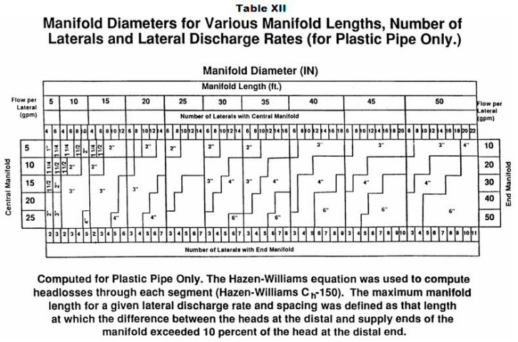
(k) The minimum inside diameter of the pressure distribution laterals from the manifold shall be one (1) inch. The maximum inside diameter of the pressure distribution laterals shall be three (3) inches.
(l) Table XIII, as follows, may be used to calculate pipe volumes:
| Table XIII - Pipe Volume for Various Diameter Pipes (gal/ft) | ||||||
| Pipe Diameter (in) | 1 | 1 1/4 | 1 1/2 | 2* | 3* | 4* |
| Volume (gal/ft) | .045 | .078 | .106 | .174 | .384 | .650 |
| *These diameters and pipe volumes are for calculating the total volume of the effluent force main. They are not used for calculating volumes of pressure distribution laterals. | ||||||
(m) The pressure distribution laterals shall have one (1) row of holes spaced in accordance with Table XIV, as follows:
| Table XIV - Soil Loading Rates Versus Pressure Distribution Lateral Hole Spacing for Subsurface Trench Pressure Distribution Systems | |
| Soil Loading Rates: Gallons per Day per Square Foot | Lateral Hole Spacing Feet Between Holes |
| 1.2 | 3 |
| 0.75 | 3 to 5 |
| 0.5 and 0.6 | 3 to 6 |
| 0.25 and 0.3 | 3 to 7 |
(n) The holes in the pressure distribution laterals shall be placed in the trenches facing down, and all burrs shall be removed from the edges of the holes.
(o) The hole size in the pressure distribution laterals shall be one-fourth (1/4) inch.
(p) The perforation discharge rate shall be determined in accordance with the formula used to compute the flow from a hole in the pressure distribution lateral at inline head as follows:

| Where: | Q | = | the volume of the flow from the hole. |
| d | = | the diameter of the hole in the pipe. | |
| H | = | the inline head at the hole. | |
| Table XV, as follows, gives the discharge rates at varying heads that would be obtained using the formula above in which "d" equals one-fourth (1/4) inch diameter holes: | |||
| Table XV - Perforation Discharge Rates in GPM at Varying Inline Heads for 1/4 Inch Diameter Hole Size | |
| Inline Head (feet) | Perforation Discharge Rate (gallons per minute) |
| 2.5 | 1.17 |
| 3.0 | 1.28 |
| 3.5 | 1.38 |
| 4.0 | 1.47 |
| 4.5 | 1.56 |
| 5.0 | 1.65 |
| 5.5 | 1.73 |
(q) Effluent pump selection for soil absorption systems using pressure distribution shall be based on the manufacturer's pump curves for the required pump discharge rate at the total head imposed on the pump. The pump discharge rate for level on-site sewage systems is calculated by using the following formula:
| Pump discharge rate = Perforation discharge rate × total number of perforations |
| To obtain the pump discharge rate required for sloping sites, the rate must be calculated individually for each pressure distribution lateral using the pump discharge rate formula based on the pressure on that line, and the sum of the calculated discharge rates determined for each individual line. |
(r) The end of each pressure distribution lateral shall be capped, and a one-fourth (1/4) inch hole shall be drilled in the upper half of the end cap.
(s) All joints, including the end cap, shall withstand the pressures exerted on them.
(Indiana State Department of Health;
410 IAC 6-10.1-87 Elevated sand mound on-site sewage systems: design of the aggregate bed
Authority: Affected: IC 16-19-3-4
Sec. 87. (a) The size of the aggregate bed shall be determined from the following:
(1) The minimum area of the aggregate bed shall be calculated as:
| minimum aggregate bed area (ft2) (AB) | = | DDF (gpd) | |
| 1.2 gpd/ft2 |
(2) The dimensions of the aggregate bed shall be as long and narrow as the site allows, while not exceeding the maximum bed width calculated in subdivision (3)(A).
(3) The maximum width of the aggregate bed shall meet the following requirements:
| (A) The maximum aggregate bed width (ft.)(ABW) = 0.83 ft2/gpd | 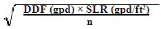 |
|||
| where 0.83 is a conversion factor (ft2/gpd) | DDF (gpd) | n | ||
| SLR is soil loading rate, and | < 1500 | 3 | ||
| where: DDF is design daily flow, and | 1501-3000 | 4 | ||
| n is determined by the DDF in this chart | 3001-4000 | 5 | ||
| This number may be rounded down to the nearest whole number. | ||||
(B) For on-site sewage systems with a DDF of seven hundred fifty (750) gallons per day or less, the width of the aggregate bed shall be at least four (4) feet and not greater than ten (10) feet. The aggregate bed width shall not exceed the maximum bed width calculated in clause (A).
(C) For on-site sewage systems with a DDF of greater than seven hundred fifty (750) gallons per day, the following apply:
(i) If the soil loading rate is fifty-hundredths (0.50) gallons per day per square foot (gpd/ft2) or less, the width of the aggregate bed shall be not greater than fifteen (15) feet, and shall not exceed the maximum bed width calculated in clause (A).
(ii) If the soil loading rate is greater than fifty-hundredths (0.50) gallons per day per square foot (gpd/ft2), the width of the aggregate bed shall be not greater than twenty (20) feet, and shall not exceed the maximum bed width calculated in clause (A).
(4) The minimum length of the aggregate bed shall be calculated as:
| Minimum length of the aggregate bed (ABL) | = | Minimum aggregate bed area (AB) | |
| Maximum aggregate bed width (ABW) |
(5) The depth of the aggregate bed shall be at least the sum of:
(A) at least six (6) inches of aggregate below the pressure distribution lateral;
(B) the outside diameter of the pressure distribution lateral; and
(C) at least two (2) inches of aggregate above the pressure distribution lateral.
(b) The aggregate bed shall be installed on the INDOT Specification 23 sand in the basal area, as listed in Table XVI in section 88(j) of this rule.
(c) The location of the aggregate bed shall be:
(1) for sites with slopes of one-half percent (1/2%) or less, with its length positioned along the long axis in the center of the basal area; and
(2) for sites with slopes greater than one-half percent (1/2%) and less than or equal to six percent (6%), with its length positioned along the long axis at the upslope side of the basal area.
(d) The design of the aggregate bed shall comply with the following:
(Indiana State Department of Health;
(1) The long axis of the aggregate bed shall be constructed along the contours of the absorption system site.
(2) The bottom of the aggregate bed shall be level along its length and width.
(3) Aggregate used in the aggregate bed shall comply with the requirements of section 76 of this rule.
(4) If more than one (1) aggregate bed is constructed, each of the aggregate beds shall be equal in area.
(5) A one (1) foot wide border of INDOT Specification 23 sand, level with the top of the aggregate bed, shall surround the aggregate bed.
Figure 1, as follows, presents a visual depiction of the location of the aggregate bed within the basal area:
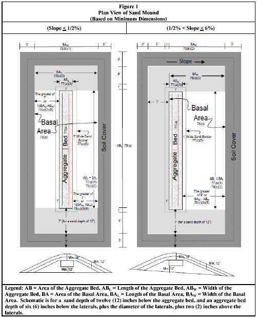
410 IAC 6-10.1-88 Elevated sand mound on-site sewage systems: design of basal area
Authority: Affected: IC 16-19-3-4
Sec. 88. (a) The dimensions of the basal area shall be as long and narrow as the site allows, in compliance with the requirements of subsection (c).
(b) Numerical dimensions provided in this section for basal area and elevated sand mound size are rounded up to the nearest whole number.
(c) The size of the basal area shall be determined from the following:
(1) The minimum size of the basal area shall be calculated as:
| Minimum basal area (ft2)(BA) | = | DDF (gpd) | |
| soil loading rate (SLR) |
using the soil loading rates from Table VI in section 80(b)(7) of this rule. The soil loading rate used for this computation shall be the soil loading rate of the most restrictive horizon in the first twenty (20) inches below the ground surface.
(2) The minimum length for the basal area (BAL) shall equal the length of the aggregate bed (ABL).
(3) The minimum width of the basal area (BAW) shall be calculated as the greater of:
| (A) | Minimum basal area width = | minimum basal area (ft.2) (BA) | ; or | |
| length of aggregate bed (ft) (ABL) | ||||
| (B) | Slope | Minimum Basal Area Width (BAW) | ||
| 0% < slope < 1/2% | Aggregate bed width + 14 ft. | |||
| 1/2% < slope < 6% | Aggregate bed width + 9 ft. | |||
| (C) The dimensions determined from clause (A) or (B) for the INDOT Specification 23 sand shall maintain a minimum sideslope grade of three-to-one (3:1). | ||||
(d) The location of the basal area within the elevated sand mound shall be:
(1) on sites with slopes of one-half percent (1/2%) or less, the area under the aggregate bed and extending an equal distance from each side along the length of the aggregate bed; and
(2) on sites with slopes greater than one-half percent (1/2%) and less than or equal to six percent (6%), the area under the aggregate bed and extending directly downslope from the aggregate bed.
(e) The design of the basal area shall be for:
(1) sites with slopes one-half percent (1/2%) or less; or
(2) sites with slopes greater than one-half percent (1/2%) and less than or equal to six percent (6%).
(f) The basal area shall be constructed on the tilled surface of the soil absorption system site in accordance with the provisions of section 94 of this rule.
(g) The long axis of the basal area and elevated sand mound shall be constructed along the contour of the soil absorption system site.
(h) The minimum depth of the INDOT Specification 23 sand under the aggregate bed shall be twelve (12) inches.
(i) The INDOT Specification 23 sand shall have a minimum final grade on all sides of three-to-one (3:1).
(j) The INDOT Specification 23 sand used in the elevated sand mound shall meet the following standard:
| Table XVI - INDOT Specification 23 Sand* | |
| Sieve Sizes | Percent (%) Passing Sieve (by Weight) |
| 3/8 in (9.50 mm) | 100 |
| No. 4 (4.75 mm) | 95 – 100 |
| No. 8 (2.36 mm) | 80 – 100 |
| No. 16 (1.18 mm) | 50 – 85 |
| No. 30 (600 μm) | 25 – 60 |
| No. 50 (300 μm) | 5 – 30 |
| No. 100 (150 μm) | 0 – 10 |
| No. 200 (75 μm) | 0 – 3 |
| *The sand shall not have more than forty-five percent (45%) retained between any two (2) consecutive sieves. | |
(k) Figure 1 in section 87(d) of this rule presents a visual depiction of the location of the basal area within the elevated sand mound.
(Indiana State Department of Health;
410 IAC 6-10.1-89 Elevated sand mound on-site sewage systems: dimensions of the elevated sand mound
Authority: Affected: IC 16-19-3-4
Sec. 89. (a) Numerical dimensions for the soil material cover from the edge of the basal area to the edge of the elevated sand mound are based on a final grade of three-to-one (3:1) (on level sites). The plan views and numerical dimensions are for a simple slope (a slope that forms a plane). Elevated sand mounds sited on complex slopes are more difficult to design and construct on contour.
(b) The minimum length of an elevated sand mound shall be the sum of the following:
(1) The length of the aggregate bed (ABL).
(2) Plus fourteen (14) feet, representing the two sideslopes of INDOT Specification 23 sand at both ends of the aggregate bed (including the one (1) foot level borders). A minimum endslope grade of three-to-one (3:1) shall be maintained on the INDOT Specification 23 sand.
(3) Plus six (6) feet, representing the soil material cover at both ends of the aggregate bed. A minimum endslope grade of three-to-one (3:1) shall be maintained on the soil cover material.
(c) The minimum width of the elevated sand mound shall be determined from the following:
(Indiana State Department of Health;
(1) On sites with slopes one-half percent (1/2%) or less, the minimum width of an elevated sand mound is the sum of the following:
(A) The basal area width (BAW) as determined in section 88(c)(3) of this rule.
(B) Plus six (6) feet, representing the soil material cover on both sides of the aggregate bed.
(2) On sites with slopes greater than one-half percent (1/2%) and less than or equal to six percent (6%), the minimum width of an elevated sand mound shall be the sum of the following:
(A) The basal area width (BAW) as determined in section 88(c)(3) of this rule.
(B) Plus seven (7) feet, representing the sideslope of INDOT Specification 23 sand on the upslope side of the aggregate bed (including the one (1) foot level border), and shall maintain a minimum sideslope grade of three-to-one (3:1).
(C) Plus six (6) feet, representing the soil material cover on both sides of the aggregate bed. A minimum sideslope grade of three-to-one (3:1) shall be maintained on the soil cover material.
410 IAC 6-10.1-90 Elevated sand mound on-site sewage systems: pressure distribution network
Authority: Affected: IC 16-19-3-4
Sec. 90. (a) The effluent force main shall drain unless it is installed below the frost line, as listed in Table IX in section 84(d) of this rule, and designed so that no effluent remains in any portion of the effluent force main located above the frost line.
(b) The effluent pump shall be sized, and its controls set, to deliver approximately one-fourth (1/4) of the DDF per dose.
(c) The liquid holding capacity of the dosing tank shall be determined as follows:
(1) If the effluent force main and manifold do not drain to the dosing tank, the dosing tank volume shall be one-fourth (1/4) of the DDF.
(2) If the effluent force main and manifold drain to the dosing tank, the dosing tank volume shall be one-fourth (1/4) of the DDF plus the volume of the effluent force main.
(3) Additional dosing tank capacity must be provided to:
(A) keep the dosing tank effluent pump submerged at all times; and
(B) provide sufficient freeboard for a high water alarm.
(d) The minimum inside diameter of the effluent force main shall be one and one-half (1 1/2) inches. The maximum inside diameter of the effluent force main shall be four (4) inches.
(e) Tables X and XI in section 84(h) of this rule, or equivalent tables provided by the pipe manufacturer, shall be used in determining friction losses in the effluent force main and manifold when plastic pipe is used. The Hazen-Williams equation may also be used to determine friction loss in the effluent force main and manifold.
(f) The design of the pressure distribution network shall meet the following requirements:
(1) The effluent force main shall approach the elevated sand mound as follows:
(A) On sites with slopes of one-half percent (1/2%) or less, from either end.
(B) On sites with slopes greater than one-half percent (1/2%) and less than or equal to six percent (6%), from the upslope side. If approach from the upslope side of the elevated sand mound is not possible due to site limitations, the effluent force main may approach from either end.
(2) The design (location) of the effluent force main shall provide for minimal disturbance of the basal area during installation.
(g) Manifolds shall be installed between the effluent force main and the pressure distribution laterals as follows:
(1) The manifold shall be located in the aggregate bed.
(2) The manifold pipe shall:
(A) for on-site sewage systems with a DDF of seven hundred fifty (750) gallons per day or less, have a diameter of two (2) inches; or
(B) for on-site sewage systems with a DDF of greater than seven hundred fifty (750) gallons per day, have the same diameter as the effluent force main or a diameter of two (2) inches, whichever is greater, but no greater than four (4) inches.
(h) The pressure distribution laterals shall meet the following requirements:
(1) Each pressure distribution lateral shall connect directly to the manifold.
(2) The length of each lateral shall be calculated as: Lateral length (LLat) = (ABL- 3)/2
(3) No single pressure distribution lateral (from the manifold to the end cap) shall exceed fifty-five (55) feet in length.
(4) The diameter of the pressure distribution laterals shall be determined from Table XVII, as follows:
| Table XVII - Pressure Distribution Lateral Diameter for Elevated Sand Mounds* | |||
| Lateral Length, L (ft.) | L < 25 ft. | 25 ft. < L < 40 ft. | 40 ft. < L < 55 ft. |
| Diameter (in.) | 1 in. | 1 1/4 in. | 1 1/2 in. |
| *Pressure distribution lateral diameters for one-quarter (1/4) in. holes spaced at three (3) ft. on centers. | |||
(5) Pressure distribution laterals shall have one (1) row of holes with three (3) feet on center spacing.
(6) The holes in the pressure distribution laterals shall be one-quarter (1/4) inch in diameter.
(7) The number of holes per lateral, including the hole in the end cap, shall be calculated as:
Number of holes per lateral = (LLat – 1.50/3) + X;
where: X = 1 if R < 0.5; and X = 2 if R > 0.5; and
R = the remainder from the mathematical equation.
(8) The first hole in each lateral shall be eighteen (18) inches from the center of the manifold.
(9) The last hole in the pressure distribution lateral before the end cap shall be at not less than eighteen (18) inches and not more than thirty-six (36) inches from the end cap.
(10) The end of each lateral shall be capped, and a one-fourth (1/4) inch hole shall be drilled in the upper half of the end cap.
(11) Burrs shall be removed from the edges of all holes and from the interiors of all laterals.
(12) All pressure distribution laterals shall be:
(A) at the same elevation; and
(B) level throughout their lengths.
(13) The pressure distribution laterals shall be placed in the aggregate bed with all holes, except the end cap holes, facing down.
(i) Pressure distribution laterals shall be laid out as shown in Figure 2, as follows:
(1) The separation distance between pressure distribution laterals shall be not less than twenty-four (24) inches and not more than thirty-six (36) inches.
(2) Pressure distribution laterals shall be located not less than twelve (12) inches and not more than eighteen (18) inches from the sides of the aggregate bed along the length of the lateral.
(3) Pressure distribution laterals shall be attached to the manifold using nondirectional fittings designed to withstand the required pressures exerted on them.
(4) The end of each pressure distribution lateral with the hole in the end cap of the lateral shall be eighteen (18) inches from the end of the aggregate bed.
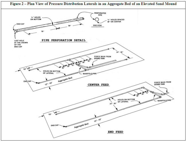
(5) All joints, including the end caps, shall withstand the pressures exerted on them.
(j) Effluent pump selection for elevated sand mound on-site sewage systems shall be based on the manufacturer's pump curves for the required pump discharge rate at the total dynamic head imposed on the pump, as follows:
(Indiana State Department of Health;
(1) The total discharge rate of the effluent pump shall be the total number of one-quarter (1/4) inch holes in all laterals (including the holes in the end caps) times one and twenty-eight hundredths (1.28) gallons per minute (gpm).
(2) The total dynamic head imposed on the pump shall be the sum of the following:
(A) The design head shall be three (3) feet.
(B) Plus friction loss in the effluent force main and manifold as determined by Tables X and XI in section 84(h) of this rule when plastic pipe is used.
(C) Plus the static head which is the difference in elevation from the effluent pump and the highest point in the effluent force main or the connection to the manifold, whichever is the highest elevation.
410 IAC 6-10.1-91 Elevated sand mound on-site sewage systems: protection of the site
Authority: Affected: IC 16-19-3-4
Sec. 91. (a) Before the start of any construction on the property, the following areas must be staked out and protected from disturbance:
(1) The soil absorption system area.
(2) The dispersal area.
(3) The subsurface drainage system area.
(4) The set-aside area (if required in the approved plan).
(5) Areas designated for future expansion (if required in the approved plan).
(b) Special caution shall be taken to prevent wheeled and tracked vehicles from compacting the area selected for placement of the elevated sand mound soil absorption system before, during, and after construction, especially during wet weather. Alteration of soil structure by movement of vehicles may be grounds for rejection of the site or the on-site sewage system, or both.
(Indiana State Department of Health;
410 IAC 6-10.1-92 Elevated sand mound on-site sewage systems: requirements for system construction
Authority: Affected: IC 16-19-3-4
Sec. 92. (a) Site preparation, tilling, construction, finish grading, and soil stabilization shall:
(1) be performed in accordance with the approved plans; and
(2) not be performed when the soil is frozen.
(b) Elevated sand mound soil absorption systems, as follows, shall not be constructed during periods of wet weather when the soil is sufficiently wet at the depth of installation to exceed its plastic limit:
(Indiana State Department of Health;
(1) This applies to soils classified as the following:
(A) Sandy loam.
(B) Silt loam.
(C) Loam.
(D) Clay loam.
(E) Silty clay loam.
(F) Sandy clay.
(G) Silty clay.
(H) Clay.
(2) Sufficient samples shall be evaluated throughout the soil absorption system site, from the soil surface to the depth of tilling, to assure that the plastic limit of the soil is not exceeded.
(3) The plastic limit of a soil shall be considered to have been exceeded when the soil can be rolled between the palms of the hands to produce threads one-eighth (1/8) inch in diameter without breaking apart and crumbling.
410 IAC 6-10.1-93 Elevated sand mound on-site sewage systems: installation of the effluent force main
Authority: Affected: IC 16-19-3-4
Sec. 93. (a) To minimize disturbance of the basal area, the effluent force main must be brought above grade prior to entering the basal area and it must be extended upward through the INDOT Specification 23 sand to the point where it will enter the aggregate bed. The effluent force main shall be laid in the aggregate bed to the point of connection to the manifold.
(b) If the effluent force main is installed prior to tilling the elevated sand mound site, the following apply:
(1) The effluent force main must be installed a minimum of sixteen (16) inches below existing grade from the outlet of the dosing tank to the point where it comes up through the INDOT Specification 23 sand, outside of the basal area.
(2) The end of the effluent force main shall be fitted with a temporary vertical pipe extending at least three (3) feet above grade and temporarily capped during the construction process.
(3) The portion of the effluent force main which comes above existing grade must be bedded and stabilized properly as the sand is applied.
(c) If the effluent force main is installed after tilling of the site and placement of the INDOT Specification 23 sand, the following apply:
(Indiana State Department of Health;
(1) The excavation must be hand dug through the INDOT Specification 23 sand.
(2) Dirt, sand, and debris must be prevented from entering the effluent force main during installation.
(3) The portion of the effluent force main that is installed in the INDOT Specification 23 sand must be properly bedded and stabilized.
410 IAC 6-10.1-94 Elevated sand mound on-site sewage systems: preparation of the site
Authority: Affected: IC 16-19-3-4
Sec. 94. (a) For all elevated sand mound sites, the following requirements shall be met for site preparation:
(1) Vegetation that would interfere with the soils evaluation, system layout, or system construction shall be cut and removed (not scraped) prior to installation without causing compaction.
(2) Trees shall be cut off at the ground surface and removed, with only stumps left in place. The department may require scarring of the tree stumps.
(3) Tree roots that protrude above the tilled surface shall be cut off and removed without causing compacted soil material.
(4) The portion of the elevated sand mound site receiving INDOT Specification 23 sand shall be tilled along the contour of the site to a depth of seven (7) inches to fourteen (14) inches with a moldboard or chisel plow, or a bulldozer with a ripper. A backhoe may be used to till sites with special considerations as noted in subsection (b). The department or local health department may require field supervision of tilling operations. The following requirements apply:
(A) If a chisel plow or a bulldozer with a ripper is used, tillage shall be across the site along the contour of the site.
(B) If a moldboard plow is used:
(i) it shall have at least two (2) bottoms and make only one (1) pass across the area, along the contour of the site; and
(ii) on sites with slopes greater than one-half percent (1/2%), the furrows shall be turned upslope.
(b) For wooded sites, and sites that limit the use of larger equipment, a backhoe may be used to till the site if the following requirements are met:
(1) The use of a backhoe shall be approved, in writing, by the department or local health department.
(2) Tilling shall be performed along the contour of the site.
(3) The surface of the ground shall be tilled with the chisel teeth fitted onto the backhoe bucket.
(4) The backhoe shall remain on untilled soil.
(5) If a moldboard plow, chisel plow, or bulldozer with a ripper is used to till the site, the provisions of subsection (a)(4) must be utilized.
(c) If compacted soil material is identified in the soil from the surface to a depth of twelve (12) inches, tilling of the soil shall be to a depth of at least two (2) inches below the bottom of the compacted soil material. If compacted soil material is identified in the soil at a depth greater than twelve (12) inches, the site is unsuitable for elevated sand mound construction.
(Indiana State Department of Health;
410 IAC 6-10.1-95 Elevated sand mound on-site sewage systems: placement of the sand on the basal area
Authority: Affected: IC 16-19-3-4
Sec. 95. (a) The basal area shall be covered using sand that meets the requirements listed in Table XVI in section 88(j) of this rule.
(b) INDOT Specification 23 sand shall be placed on the tilled area immediately after tilling the site to protect the tilled surfaces from damage by precipitation.
(c) The depth of the INDOT Specification 23 sand under the aggregate bed shall be at least twelve (12) inches (on sites with slopes greater than one-half percent (1/2%), the depth of INDOT Specification 23 sand beneath the downslope side of the aggregate bed will be greater than twelve (12) inches).
(d) INDOT Specification 23 sand shall be placed on the tilled surface as follows:
(1) On sites with slopes one-half percent (1/2%) or less, from the ends of the elevated sand mound.
(2) On sites with slopes greater than one-half percent (1/2%) and less than or equal to six percent (6%), from the ends or upslope edge of the elevated sand mound.
(e) At least six (6) inches of INDOT Specification 23 sand shall be kept between the vehicle tracks or tires and the tilled soil of the site.
(f) The depth of INDOT Specification 23 sand around the aggregate bed shall be the sum of:
(1) the depth of the sand under the aggregate bed; and
(2) the depth of the aggregate bed.
(g) A one (1) foot wide border of INDOT Specification 23 sand shall surround the aggregate bed, level with the top of the aggregate bed.
(Indiana State Department of Health;
410 IAC 6-10.1-96 Elevated sand mound on-site sewage systems: construction of the aggregate bed
Authority: Affected: IC 16-19-3-4
Sec. 96. (a) The surface of the INDOT Specification 23 sand at the sand/aggregate interface shall be smooth and free of ruts and depressions before the placement of the aggregate.
(b) The depth of aggregate in the aggregate bed from side to side and end to end shall be at least:
(1) six (6) inches below the pressure distribution laterals;
(2) plus the outside diameter of the pressure distribution laterals;
(3) plus two (2) inches above the pressure distribution laterals.
(c) The aggregate bed shall be covered with a barrier material which meets the minimum requirements of section 77 of this rule. The barrier material shall cover the aggregate bed from side to side and from end to end.
(Indiana State Department of Health;
410 IAC 6-10.1-97 Elevated sand mound on-site sewage systems: placement of the soil material and final grade
Authority: Affected: IC 16-19-3-4
Sec. 97. (a) If the ground surface along the perimeter of the INDOT Specification 23 sand was not tilled during preparation of the elevated sand mound site, the perimeter shall be prepared by tilling in accordance with the requirements of section 94 of this rule.
(b) The soil material cover shall:
(1) have a texture other than sand or loamy sand;
(2) be capable of sustaining plant growth; and
(3) be placed on the INDOT Specification 23 sand without causing compacted soil material.
(c) Prior to placement of the soil cover material, the surface of the INDOT Specification 23 sand shall be prepared by:
(1) maintaining a minimum grade of at least three-to-one (3:1); and
(2) preparing the surface of the INDOT Specification 23 sand so that it is smooth and free of ruts and depressions.
(d) The aggregate and sand of the elevated sand mound shall be covered with a minimum of twelve (12) inches of soil material. An additional six (6) inches of that soil material, for a total of eighteen (18) inches, shall be placed over the center line of the long axis of the aggregate bed and crowned to promote surface runoff away from the elevated sand mound.
(e) Soil material shall be placed on the tilled portion of the sand perimeter and graded according to the requirements of subsection (f).
(f) The soil material cover shall have a minimum final grade on all sides of three-to-one (3:1).
(g) The elevated sand mound shall be seeded or sodded with grasses adapted to the area. If seeded, the elevated sand mound shall be protected by a cover of straw, burlap, or some other biodegradable material that will protect it against erosion.
(Indiana State Department of Health;
410 IAC 6-10.1-98 Abandonment of an on-site sewage system
Authority: Affected: IC 16-19-3-4
Sec. 98. (a) When the use of an on-site sewage system is discontinued, the following procedure must be followed for all tanks and electrical service:
(1) Electrical power must be disconnected at the source. All controls and panels must be removed.
(2) All above ground electrical lines (including buried service lines) that will not be used for other purposes must be removed.
(3) A licensed septic tank cleaner must pump all contents from all tanks in the on-site sewage system.
(4) The tanks must either be:
(A) removed or the lids crushed into the tanks and the holes or tanks must be backfilled with debris-free sand or other granular material, concrete, or soil material that is compacted to prevent settling. (If a sand mound is being abandoned, sand, aggregate and soil cover from the sand mound may be used for filling the tank or tanks); or
(B) filled with flowable fill.
(5) Properly grade and establish vegetative cover.
(b) The components of the soil absorption system may be left intact, if there are no plans to use the area for other purposes. Vegetative cover must be maintained.
(c) If effluent has surfaced, those areas must be covered with hydrated lime followed by top soil and a vegetative cover.
(d) If components of the soil absorption system are to be removed, the following procedure must be used:
(1) A licensed septic tank cleaner must pump all contents from all distribution boxes in the on-site sewage system.
(2) Allow sufficient time after the on-site sewage system is taken out of service and the tanks pumped to make sure the entire soil absorption system is completely dry.
(3) A contractor must remove the distribution network, aggregate and sand (if any) from the site.
(4) The contractor must dispose of the materials at a licensed landfill.
(5) The site must be properly graded and a vegetative cover established.
(e) Written documentation of tank abandonment must be provided to the department and the local health department by the owner in the form of a receipt from the contractor.
(Indiana State Department of Health;
410 IAC 6-10.1-99 Matters incorporated by reference
Authority: Affected: IC 16-19-3-4
Sec. 99. (a) Bulletin SE 11, "The Sanitary Vault Privy", 1986 Edition, is incorporated by reference as part of this rule. It is available at the department at 2 North Meridian Street, Indianapolis, Indiana 46204.
(b) NSF/ANSI Standard 40-2010 and Standard 46-2010a are incorporated by reference as part of this rule. Two (2) copies of each standard are available for reference in the files of the department. Copies of the standards may be obtained by mailing a request to the National Sanitation Foundation, 789 North Dixboro Road, P.O. Box 130140, Ann Arbor, Michigan 48113-0140, or at:
www.techstreet.com/cgi-bin/joint.cgi/nsf
(c) ASTM Standards C 923-08, C 990-09, C 1644-06, D 1527-99 (Reapproved 2005), D 1785-06, D 2241-09, D 2282-99 (Reapproved 2005), D 2661-11, D 2665-12, D 2680-01 (Reapproved 2009), D 2729-11, D 2751-05, D 3034-08, D 4355-07, D 4491-99a (Reapproved 2009), D 4533-11, D 4632-08, D 4751-04, D 6241-04 (Reapproved 2009), F 405-05, F 480-12, F 667-12, F 810-07, and F 891-10 are incorporated by reference as part of this rule. Two (2) copies of each standard are available for reference in the files of the department. ASTM standards may be obtained at:
http://www.astm.org/Standard/index.shtml
(d) AASHTO Standard M252-09 is incorporated by reference as part of this rule. Two (2) copies of the standard are available for reference in the files of the department. This standard may be obtained at:
http://www.transportation.org
(e) NRCS Standard 606, September 2003 is incorporated by reference as part of this rule. Two (2) copies of the standard are available for reference in the files of the department. This standard may be obtained at:
http://efotg.nrcs.usda.gov/references/public/AL/tg606.pdf
(f) INDOT 2012 Standard Specifications, Section 904, Aggregates is incorporated by reference as part of this rule. Two (2) copies of the standard are available for reference in the files of the department. The standard may be obtained at:
http://www.in.gov/dot/div/contracts/standards/book/sep11/sep.htm
(g) NEMA 250-2008 is incorporated by reference as part of this rule. Two (2) copies of the standard are available for reference in the files of the department. The standard may be obtained at http://webstore.ansi.org/RecordDetail.aspx?sku=NEMA%20250-2008 & source=google & adgroup=nema & gclid=CKe9-66a368CFSWFQAodnnii_A.
(Indiana State Department of Health;
SECTION 2. 410 IAC 6-10 IS REPEALED.
LSA Document #12-157(F)
Notice of Intent: 20120404-IR-410120157NIA
Proposed Rule: 20120620-IR-410120157PRA
Hearing Held: July 16, 2012
Approved by Attorney General: October 10, 2012
Approved by Governor: October 19, 2012
Filed with Publisher: October 19, 2012, 2:07 p.m.
Documents Incorporated by Reference: Bulletin SE 11, "The Sanitary Vault Privy," Indiana State Department of Health (1986); Standard NSF/ANSI 40-2010, Residential Wastewater Treatment Systems, National Sanitation Foundation International/American National Standards Institute; Standard NSF/ANSI 46-2010a, Evaluation of Components and Devices Used in Wastewater Treatment Systems, National Sanitation Foundation International/American National Standards Institute; Standard C 923-08, Standard Specification for Resilient Connectors Between Reinforced Concrete Manhole Structures, Pipes, and Laterals, American Society for Testing and Materials; Standard C 990-09, Standard Specification for Joints for Concrete Pipe, Manholes, and Precast Box Sections Using Preformed Flexible Joint Sealants, American Society for Testing and Materials; Standard C 1644-06, Standard Specification for Resilient Connectors Between Reinforced Concrete On-Site Wastewater Tanks and Pipes, American Society for Testing and Materials; Standard D 1527-99 (Reapproved 2005), Standard Specification for Acrylonitrile-Butadiene-Styrene (ABS) Plastic Pipe, Schedules 40 and 80, American Society for Testing and Materials; Standard D 1785-06, Standard Specification for Poly(Vinyl Chloride) (PVC) Plastic Pipe, Schedules 40, 80, and 120, American Society for Testing and Materials; Standard D 2241-09, Standard Specification for Poly(Vinyl Chloride) (PVC) Pressure-Rated Pipe (SDR Series),
American Society for Testing and Materials; Standard D 2282-99 (Reapproved 2005), Standard Specification for Acrylonitrile-Butadiene-Styrene (ABS) Plastic Pipe (SDR-PR), American Society for Testing and Materials; Standard D 2661-11, Standard Specification for Acrylonitrile-Butadiene-Styrene (ABS) Schedule 40 Plastic Drain, Waste, and Vent Pipe and Fittings, American Society for Testing and Materials; Standard D 2665-12, Standard Specification for Poly(Vinyl Chloride) (PVC) Plastic Drain, Waste, and Vent Pipe and Fittings, American Society for Testing and Materials; Standard D 2680-01 (Reapproved 2009), Standard Specification for Acrylonitrile-Butadiene-Styrene (ABS) and Poly(Vinyl Chloride) (PVC) Composite Sewer Piping, American Society for Testing and Materials; Standard D 2729-11, Standard Specification for Poly(Vinyl Chloride) (PVC) Sewer Pipe and Fittings, American Society for Testing and Materials; Standard D 2751-05, Standard Specification for Acrylonitrile-Butadiene-Styrene (ABS) Sewer Pipe and Fittings, American Society for Testing and Materials; Standard D 3034-08, Standard Specification for Type PSM Poly(Vinyl Chloride) (PVC) Sewer Pipe and Fittings, American Society for Testing and Materials; Standard D 4355-07, Standard Test Method for Deterioration of Geotextiles by Exposure to Light, Moisture and Heat in a Xenon Arc Type Apparatus, American Society for Testing and Materials; Standard D 4491-99a (Reapproved 2009), Standard Test Methods
for Water Permeability of Geotextiles by Permittivity, American Society for Testing and Materials; Standard D 4533-11, Standard Test Method for Trapezoid Tearing Strength of Geotextiles, American Society for Testing and Materials; Standard D 4632-08, Standard Test Method for Grab Breaking Load and Elongation of Geotextiles, American Society for Testing and Materials; Standard D 4751-04, Standard Test Method for Determining Apparent Opening Size of a Geotextile, American Society for Testing and Materials; Standard D 6241-04 (Reapproved 2009), Standard Test Method for the Static Puncture Strength of Geotextiles and Geotextile-Related Products Using a 50-mm Probe, American Society for Testing and Materials; Standard F 405-05, Standard Specification for Corrugated Polyethylene (PE) Pipe and Fittings, American Society for Testing and Materials; Standard F 480-12, Standard Specification for Thermoplastic Well Casing Pipe and Couplings Made in Standard Dimension Ratios (SDR), SCH 40 and SCH 80, American Society for Testing and Materials; Standard F 667-12, Standard Specification for 3 through 24 in. Corrugated Polyethylene Pipe and Fittings, American Society for Testing and Materials; Standard F 810-07, Standard Specification for Smoothwall Polyethylene (PE) Pipe for Use in Drainage and Waste Disposal Absorption Fields, American Society for Testing and Materials; Standard F 891-10, Standard Specification for Coextruded Poly(Vinyl Chloride) (PVC) Plastic Pipe
With a Cellular Core, American Society for Testing and Materials; Standard M 252-09, Standard Specification for Corrugated Polyethylene Drainage Pipe, American Association of State Highway and Transportation Officials; Code 606, Natural Resources Conservation Service Conservation Practice Standard Subsurface Drain (Ft. ), United States Dept. of Agriculture, Natural Resources Conservation Service (September 2003); Indiana Dept. of Transportation Standard Specifications, Section 904, Aggregates, Indiana Dept. of Transportation (2012); Standard 250-2008, Enclosures for Electrical Equipment (1000 Volts Maximum), National Electrical Manufacturers Association
Small Business Regulatory Coordinator: Kelly MacKinnon, Indiana State Department of Health, 2 North Meridian Street, Section 3H-99, Indianapolis, Indiana 46204, (317) 233-7316, kmackinnon@isdh.in.gov
Posted: 11/14/2012 by Legislative Services Agency
DIN: 20121114-IR-410120157FRA
Composed: Apr 25,2024 3:09:07PM EDT
A PDF version of this document.