 |
|
N1101.3 Identification. Materials, systems and equipment shall be identified in a manner that will allow a determination of compliance with the applicable provisions of this chapter.
N1101.4 Building thermal envelope insulation. An R-value identification mark shall be applied by the manufacturer to each piece of building thermal envelope insulation 12 inches (305 mm) or more wide. Alternately, the insulation installers shall provide a certification listing the type, manufacturer and R-value of insulation installed in each element of the building thermal envelope. For blown or sprayed insulation (fiberglass and cellulose), the initial installed thickness, settled thickness, settled R-value, installed density, coverage area and number of bags installed shall be listed on the certification. For sprayed polyurethane foam (SPF) insulation, the installed thickness of the area covered and R-value of installed thickness shall be listed on the certificate. The insulation installer shall sign, date and post the certificate in a conspicuous location on the job site.
N1101.4.1 Blown or sprayed roof/ceiling insulation. The thickness of blown in or sprayed roof/ceiling insulation (fiberglass or cellulose) shall be written in inches (mm) on markers that are installed at least one for every 300 ft2 (28m2) throughout the attic space. The markers shall be affixed to the trusses or joists and marked with the minimum initial installed thickness with numbers a minimum of 1 inch (25 mm) high. Each marker shall face the attic access opening. Spray polyurethane foam thickness and installed R-value shall be listed on the certificate provided by the insulation installer.
N1101.4.2 Insulation mark installation. Insulating materials shall be installed such that the manufacturer's R-value mark is readily observable upon inspection.
N1101.5 Fenestration product rating. U-factors of fenestration products (windows, doors and skylights) shall be determined in accordance with NFRC 100 by an accredited, independent laboratory, and labeled and certified by the manufacturer. Products lacking such a labeled U-factor shall be assigned a default U-factor from Tables N1101.5(1) and N1101.5(2).
N1101.6 Insulation product rating. The thermal resistance (R-value) of insulation shall be determined in accordance with the 16 CFR 460 as in effect on March 1, 2011, in units of h • ft2 • °F/Btu at a mean temperature of 75°F (24°C).
N1101.7 Installation. All materials, systems and equipment shall be installed in accordance with the manufacturer's installation instructions and the provisions of this chapter.
N1101.7.1 Protection of exposed foundation insulation. Insulation applied to the exterior of basement walls, crawl space walls and the perimeter of slab-on-grade floors shall have a rigid, opaque and weather-resistant protective covering to prevent the degradation of the insulation's thermal performance. The protective covering shall cover the exposed exterior insulation and extend a minimum of six (6) inches (152 mm) below grade.
N1101.8 Certificate. A permanent certificate shall be posted on or in the electrical distribution panel. The certificate shall not cover or obstruct the visibility of the circuit directory label, service disconnect label or other required labels. The certificate shall be completed by the builder or registered design professional. The certificate shall list the predominant R-values of insulation installed in or on ceiling/roof, walls, foundation (slab, basement wall, crawl space wall and/or floor), ducts outside conditioned spaces, and U-factors for fenestration. Where there is more than one value for each component, the certificate shall list the value covering the largest area. The certificate shall list the types and efficiencies of heating, cooling and service water heating equipment. Where a gas-fired unvented room heater, electric furnace, and/or baseboard electric heater is installed in the residence, the certificate shall list "gas-fired unvented room heater", "electric furnace", or "baseboard electric heater" as appropriate. An efficiency shall not be listed for gas-fired unvented room heaters, electric furnaces, or electric baseboard heaters.
SECTION N1102; BUILDING THERMAL ENVELOPE
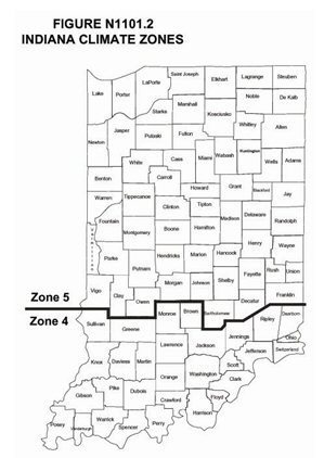
N1102.1 Insulation and fenestration criteria. The building thermal envelope shall meet the requirements of Table N1102.1 based on the climate zone specified in Table N1101.2.
N1102.1.1 R-value computation. Insulation material used in layers, such as framing cavity insulation and insulating sheathing, shall be summed to compute the component R-value. The manufacturer's settled R-value shall be used for blown insulation. Computed R-values shall not include an R-value for other building materials or air films.
N1102.1.2 U-factor alternative. An assembly with a U-factor equal to or less than that specified in Table N1102.1.2 shall be permitted as an alternative to the R-value in Table N1102.1.
N1102.1.3 Total UA alternative. If the total building thermal envelope UA (sum of U-factor times assembly area) is less than or equal to the total UA resulting from using the U-factors in Table N1102.1.2 (multiplied by the same assembly area as in the proposed building), the building shall be considered in compliance with Table N1102.1. The UA calculation shall be done using a method consistent with the Indiana Energy Conservation Code,
N1102.2 Specific insulation requirements.
N1102.2.1 Ceilings with attic spaces. When Section N1102.1 would require R-38 in the ceiling, R-30 shall be deemed to satisfy the requirement for R-38 wherever the full height of uncompressed R-30 insulation extends over the wall top plate at the eaves. Similarly R-38 shall be deemed to satisfy the requirement for R-49 wherever the full height of uncompressed R-38 insulation extends over the wall top plate at the eaves. This reduction shall not apply to the U-factor alternative approach in Section N1102.1.2 and the Total UA alternative in Section N1102.1.3.
N1102.2.2 Ceilings without attic spaces. Where Section N1102.1 would require insulation levels above R-30 and the design of the roof/ceiling assembly does not allow sufficient space for the required insulation, the minimum required insulation for such roof/ceiling assemblies shall be R-30. This reduction of insulation from the requirements of N1102.1 shall be limited to five hundred (500) square feet (46 m2) or twenty (20) percent of the total insulated ceiling area, whichever is less. This reduction shall not apply to the U-factor alternative approach in Section N1102.1.2 and the Total UA alternative in Section N1102.1.3.
N1102.2.3 Access hatches and doors. Access hatches from conditioned spaces to unconditioned spaces (e.g., attics and crawl spaces) shall be weatherstripped and insulated to a level equivalent to the insulation on the surrounding surfaces. Access shall be provided to all equipment which prevents damaging or compressing the insulation. A wood framed or equivalent baffle or retainer is required to be provided when loose fill insulation is installed, the purpose of which is to prevent the loose fill insulation from spilling into the living space when the attic access is opened and to provide a permanent means of maintaining the installed R-value of the loose fill insulation.
N1102.2.4 Mass walls. Mass walls, for the purposes of this chapter, shall be considered above-grade walls of concrete block, concrete, insulated concrete form (ICF), masonry cavity, brick (other than brick veneer), earth (adobe, compressed earth block, rammed earth) and solid timber/logs.
N1102.2.5 Steel-frame ceilings, walls and floors. Steel frame ceilings, walls and floors shall meet the insulation requirements of Table N1102.2.5 or shall meet the U-factor requirements in Table N1102.1.2. The calculation of the U-factor for a steel-frame envelope assembly shall use a series-parallel path calculation method.
N1102.2.6 Floors. Floor insulation shall be installed to maintain permanent contact with the underside of the subfloor decking.
N1102.2.7 Basement walls. Exterior walls associated with conditioned basements shall be insulated from the top of the basement wall down to ten (10) feet (3048 mm) below grade or to the basement floor, whichever is less. Walls associated with unconditioned basements shall meet this requirement unless the floor overhead is insulated in accordance with Sections N1102.1 and N1102.2.5.
N1102.2.8 Slab-on-grade floors. Slab-on-grade floors with a floor surface less than twelve (12) inches below grade shall be insulated in accordance with Table N1102.1. The insulation shall extend downward from the top of the slab on the outside or inside of the foundation wall. Insulation located below grade shall be extended the distance provided in Table N1102.1 by any combination of vertical insulation, insulation extending under the slab or insulation extending out from the building. Insulation extending away from the building shall be protected by pavement or by a minimum of ten (10) inches (254 mm) of soil. The top edge of the insulation installed between the exterior wall and the edge of the interior slab shall be permitted to be cut at a 45-degree (0.79 rad) angle away from the exterior wall.
N1102.2.9 Crawl space walls. As an alternative to insulating floors over crawl spaces, crawl space walls shall be permitted to be insulated when the crawl space is not vented to the outside. Crawl space wall insulation shall be permanently fastened to the wall and extend downward from the floor to the finished grade level and then vertically and/or horizontally for at least an additional twenty-four (24) inches (610 mm). Exposed earth in unvented crawl space foundations shall be covered with a continuous 0.1 perms or less vapor retarder. All joints of the vapor retarder shall overlap by six (6) inches (153 mm) and be sealed or taped. The edges of the vapor retarder shall extend at least six (6) inches (153 mm) up the stem wall and shall be attached to the stem wall.
N1102.2.10 Masonry veneer. Insulation shall not be required on the horizontal portion of the foundation that supports a masonry veneer.
N1102.2.11 Thermally isolated sunroom insulation. The minimum ceiling insulation R-values shall be R-19 in zone 4 and R-24 in zone 5. The minimum wall R-value shall be R-13 in all zones. New wall(s) separating the sunroom from conditioned space shall meet the building thermal envelope requirements.
N1102.3 Fenestration.
N1102.3.1 U-factor. An area-weighted average of fenestration products shall be permitted to satisfy the U-factor requirements.
N1102.3.2 Glazed fenestration exemption. Up to fifteen (15) square feet (1.4m2) of glazed fenestration per dwelling unit shall be permitted to be exempt from U-factor in Section N1102.1. This exemption shall not apply to the U-factor alternative approach in Section N1102.1.2 and the Total UA alternative in Section N1102.1.3.
N1102.3.3 Opaque door exemption. One side-hinged opaque door assembly up to twenty-four (24) square feet (2.22 m2) in area is exempted from the U-factor requirement in Section N1102.1. This exemption shall not apply to the U-factor alternative approach in Section N1102.1.2 and the Total UA alternative in Section N1102.1.3.
N1102.3.4 Thermally isolated sunroom U-factor. For zones 4 and 5, the maximum fenestration U-factor shall be 0.50 and the maximum skylight U-factor shall be 0.75. New windows and doors separating the sunroom from conditioned space shall meet the building thermal envelope requirements.
N1102.3.5 Replacement fenestration. Where some or all of an existing fenestration unit is replaced with a new fenestration product, including sash and glazing, the replacement fenestration unit shall meet the applicable requirements for U-factor in Table N1102.1.
N1102.4 Air leakage.
N1102.4.1 Building thermal envelope. The building thermal envelope shall be durably sealed to limit infiltration. The sealing methods between dissimilar materials shall allow for differential expansion and contraction. The following shall be caulked, gasketed, weatherstripped or otherwise sealed with an air barrier material, suitable film or solid material.
1. All joints, seams and penetrations.
2. Site-built windows, doors and skylights.
3. Openings between window and door assemblies and their respective jambs and framing.
4. Utility penetrations.
5. Dropped ceilings or chases adjacent to the thermal envelope.
6. Knee walls.
7. Walls and ceilings separating the garage from conditioned spaces.
8. Behind tubs and showers on exterior walls.
9. Common walls between dwelling units.
10. Attic access openings.
11. Rim joists junction.
12. Other sources of infiltration.
N1102.4.2 Air sealing and insulation. Building envelope, air tightness and insulation installation shall be demonstrated to comply with one of the following options given by Section N1102.4.2.1 or N1102.4.2.2.
N1102.4.2.1 Testing option. Tested air leakage is less than 7 air changes per hour (ACH) when tested with a blower door at a pressure of 0.007 psi (50 pascals). Testing shall occur after rough in and after installation of penetrations of the building envelope, including penetrations for utilities, plumbing, electrical, ventilation and combustion appliances. During testing:
1. Exterior windows and doors, fireplace and stove doors shall be closed, but not sealed;
2. Dampers shall be closed, but not sealed, including exhaust, intake, makeup air, back draft, and flue dampers;
3. Interior doors shall be open;
4. Exterior openings for continuous ventilation systems and heat recovery ventilators shall be closed and sealed;
5. Heating and cooling system(s) shall be turned off;
6. HVAC ducts shall not be sealed; and
7. Supply and return registers shall not be sealed.
N1102.4.2.2 Visual inspection option. The items listed in Table N1102.4.2, applicable to the method of construction, are field verified. Where required by local ordinance, an approved party independent from the installer of the insulation, shall inspect the air barrier and insulation.
N1102.4.3 Fireplaces. New wood-burning fireplaces shall have gasketed doors and outdoor combustion air.
N1102.4.4 Fenestration air leakage. Windows, skylights and sliding glass doors shall have an air infiltration rate of no more than 0.3 cubic foot per minute per square foot [1.5(L/s)/m2], and swinging doors no more than 0.5 cubic foot per minute per square foot [2.5(L/s)/m2], when tested according to NFRC 400 or AAMA/WDMA/CSA101/I.S.2/A440 by an accredited, independent laboratory, and listed and labeled by the manufacturer.
Exception: Site-built windows, skylights and doors.
N1102.4.5 Recessed lighting. Recessed luminaries installed in the building thermal envelope shall be sealed to limit air leakage between conditioned and unconditioned spaces. All recessed luminaries shall be IC-rated and labeled as meeting ASTM E 283 when tested at 1.57 psi (75 Pa) pressure differential with no more than 2.0 cfm (0.944 L/s) of air movement from the conditioned space to the ceiling cavity. All recessed luminaries shall be sealed with a gasket or caulk between the housing and the interior of the wall or ceiling covering.
N1102.5 Maximum fenestration U-factor. The area-weighted average maximum fenestration U-factor permitted using trade-offs from Section N1102.1.3 shall be 0.48 in zones 4 and 5 for vertical fenestration and 0.75 in zones 4 and 5 for skylights.
SECTION N1103; SYSTEMS
N1103.1 Controls. At least one thermostat shall be installed for each separate heating and cooling system.
N1103.1.1 Programmable thermostat. Where the primary heating system is a forced air furnace, at least one thermostat per dwelling unit shall be capable of controlling the heating and cooling system on a daily schedule to maintain different temperature set points at different times of the day. This thermostat shall include the capability to set back or temporarily operate the system to maintain zone temperatures down to 55°F (13°C) or up to 85°F (29°C). The thermostat shall initially be programmed with a heating temperature set point no higher than 70°F (21°C) and a cooling temperature set point no lower than 78°F (26°C).
N1103.1.2 Heat pump supplementary heat. Heat pumps having supplementary electric-resistance heat shall have controls that, except during defrost, prevent supplemental heat operation when the heat pump compressor can meet the heating load.
N1103.2 Ducts.
N1103.2.1 Insulation. Supply ducts in attics shall be insulated to a minimum of R-8. All other ducts shall be insulated to a minimum of R-6.
Exception: Ducts or portions thereof located completely inside the building thermal envelope.
N1103.2.2 Sealing. Ducts, air handlers, filter boxes and building cavities used as ducts shall be sealed. Joints and seams shall comply with Section M1601.3.1 of this code. Duct tightness shall be verified by either of the following:
1. Post-construction test: Leakage to outdoors shall be less than or equal to eight (8) cfm (3.78 L/s) per one hundred (100) ft2 (9.29 m2) of conditioned floor area or a total leakage less than or equal to twelve (12) cfm (5.66 L/s) per one hundred (100) ft2 (9.29 m2) of conditioned floor area when tested at a pressure differential of 0.1 inch w.g. (25 Pa) across the entire system, including the manufacturer's air handler end closure. All register boots shall be taped or otherwise sealed during the test.
2. Rough-in test: Total leakage shall be less than or equal to six (6) cfm (2.83 L/s) per one hundred (100) ft2 (9.29 m2) of conditioned floor area when tested at a pressure differential of 0.1 inch w.g. (25 Pa) across the roughed in system, including the manufacturer's air handler enclosure. All register boots shall be taped or otherwise sealed during the test. If the air handler is not installed at the time of the test, total leakage shall be less than or equal to four (4) cfm (1.89 L/s) per one hundred (100) ft2 (9.29 m2) of conditioned floor area.
Exception: Duct tightness test is not required if the air handler and all ducts are located within conditioned space.
N1103.2.3 Building cavities. Building framing cavities shall not be used as supply ducts.
N1103.3 Mechanical system piping insulation. Mechanical system piping capable of carrying fluids above 105°F (40°C) or below 55°F (13°C) shall be insulated to a minimum of R-3.
N1103.4 Circulating hot water systems. All circulating service hot water piping shall be insulated to at least R-2. Circulating hot water systems shall include an automatic or readily accessible manual switch that can turn off the hot water circulating pump when the system is not in use.
N1103.5 Mechanical ventilation. Outdoor air intakes and exhausts shall have automatic or gravity dampers that close when the ventilation system is not operating.
N1103.6 Equipment sizing. Heating and cooling equipment shall be sized as specified in Section M1401.3 of this code.
N1103.7 Snow-melt system controls. Snow- and ice-melting systems, supplied through energy service to the building, shall include automatic controls capable of shutting off the system when the pavement temperature is above 50°F (10°C) and no precipitation is falling and an automatic or manual control that will allow shutoff when the outdoor temperature is above 40° F (4°C).
N1103.8 Pools. Pools shall be provided with energy conserving measures in accordance with Sections N1103.8.1 through N1103.8.3.
N1103.8.1 Pool heaters. All pool heaters shall be equipped with a readily accessible on-off switch to allow shutting off the heater without adjusting the thermostat setting. Pool heaters fired by natural gas or LPG shall not have continuously burning pilot lights.
N1103.8.2 Time switches. Time switches that can automatically turn off and on heaters and pumps according to a pre-set schedule shall be installed on swimming pool heaters and pumps.
Exceptions:
1. Where public health standards require 24-hour pump operation.
2. Where pumps are required to operate solar-and-waste-heat-recovery pool heating systems.
N1103.8.3 Pool covers. Heated pools shall be equipped with a vapor retardant pool cover on or at the water surface. Pools heated to more than 90° F (32°C) shall have a pool cover with a minimum insulation value of R-12.
Exception: Pools deriving over sixty (60) percent of the energy for heating from site-recovered energy or solar energy source.
SECTION N1104; LIGHTING SYSTEMS
N1104.1 Lighting equipment. A minimum of fifty (50) percent of the lamps in permanently installed lighting fixtures shall be high-efficacy lamps.
SECTION N1105; REFERENCED STANDARDS
N1105.1 For purposes of this chapter, the following referenced standards, as amended, are applicable:
(a) AAMA/WDMA/CSA 101/I.S.2/A440-08; American Architectural Manufacturers Association, 1827 Walden Office Square, 550, Schaumburg, IL 60173.
(b) ASTM E 283-04; ASTM International, 100 Barr Harbor Drive, West Conshohocken, PA 19428.
(c) NFRC 100-2004; National Fenestration Rating Council, Inc., 8484 Georgia Avenue, Suite 320, Silver Spring, MD 20910. The edition of the documents listed in Chapter 6 for which no edition date is shown shall be the edition which was in effect on March 15, 2011.
(d) NFRC 400-2004; National Fenestration Rating Council, Inc., 8484 Georgia Avenue, Suite 320, Silver Spring, MD 20910. The edition of the documents listed in Chapter 6 for which no edition date is shown shall be the edition which was in effect on March 15, 2011.
SECTION 2.
Posted: 08/03/2011 by Legislative Services Agency DIN: 20110803-IR-675110084PRA
Composed: Apr 25,2024 10:57:46PM EDT
A PDF version of this document.
|
|||||||||||||||||||||||||||||||||||||||||||||||||||||||||||||||||||||||||||||||||||||||||||||||||||||||||||||||||||||||||||||||||||||||||||||||||||||||||||||||||||||||||||||||||||||||||||||||||||||||||||||||||||||||||||||||||||||||||||||||||||||||||||||||||||||||||||||||||||||||||||||||||||||||||||||||||||||||||||||||||||||||||||||||||||||||||||