 |

|
SECTION 11.
Authority: |
|||||||||||||||||||||||||||||||||||||||||||||||||||||||||||||||||||||||||||||||||||||||||||||||||||||||||||||||||||||||||||||||||||||||||||||||||||||||||||||||||||||||||||||||||||||||||||||||||||||||||||||||||||||||||||||||||||||||||||||||||||||||||||||||||||||||||||||||||||||||||||||||||||||||||||||||||||||||||||||||||||||||||||||||||||||||||||||||||||||||||||||||||||||||||||||||||||||||||||||||||||||||||||||||||||||||||||||||||||||||||||||||||||||||||||||||||||||||||||||||||||||||||||||||||||||||||||||||||||||||||||||||||||||||||||||||||||||||||||||||||||||||||||||||||||||||||||||||||||||||||||||||||||||||||||||||||||||||||||||||||||||||||||||||||||||||||||||||||||||||||||||||||||||||||||||||||||||||||||||||||||||||||||||||||||||||||||||||||||||||||||||||||||||||||||||||||||||||||||||||||||||||||||||||||||||||||||||||||||||||||||||||||||||||||||||||||||||||||||||||||||||||||||||||||||||||||||||||||||||||||||||||||||||||||||||||||||||||||||||||||||||||||||||||||||||||||||||||||||||||

| POOL TYPE | MINIMUM DIMENSIONS | MINIMUM WIDTH OF POOL | ||||||||
| D1 | D2 | L1 | L2 | L3 | L4 | L5 | PT. A | PT. B | PT. C | |
| 0 | * | * | * | * | * | * | * | * | * | * |
| I | 6'-0" | 7'-6" | 1'-6" | 7'-0" | 7'-6" | 6'-9" | 28'-9" | 10'-0" | 12'-0" | 10'-0" |
| II | 6'-0" | 7'-6" | 1'-6" | 7'-0" | 7'-6" | 6'-9" | 28'-9" | 12'-0" | 15'-0" | 12'-0" |
| III | 6'-10" | 8'-0" | 2'-0" | 7'-6" | 9'-0" | 6'-9" | 31'-3" | 12'-0" | 15'-0" | 12'-0" |
| IV | 7'-8" | 8'-6" | 2'-6" | 8'-0" | 10'-6" | 6'-9" | 33'-9" | 15'-0" | 18'-0" | 15'-0" |
| V | 8'-6" | 9'-0" | 3'-0" | 9'-0" | 12'-0" | 6'-9" | 36'-9" | 15'-0" | 18'-0" | 15'-0" |
| • Diving equipment is prohibited. | ||||||||||
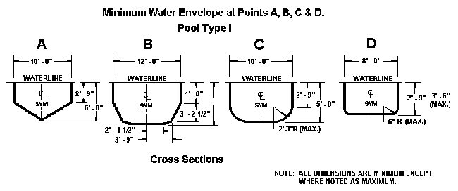
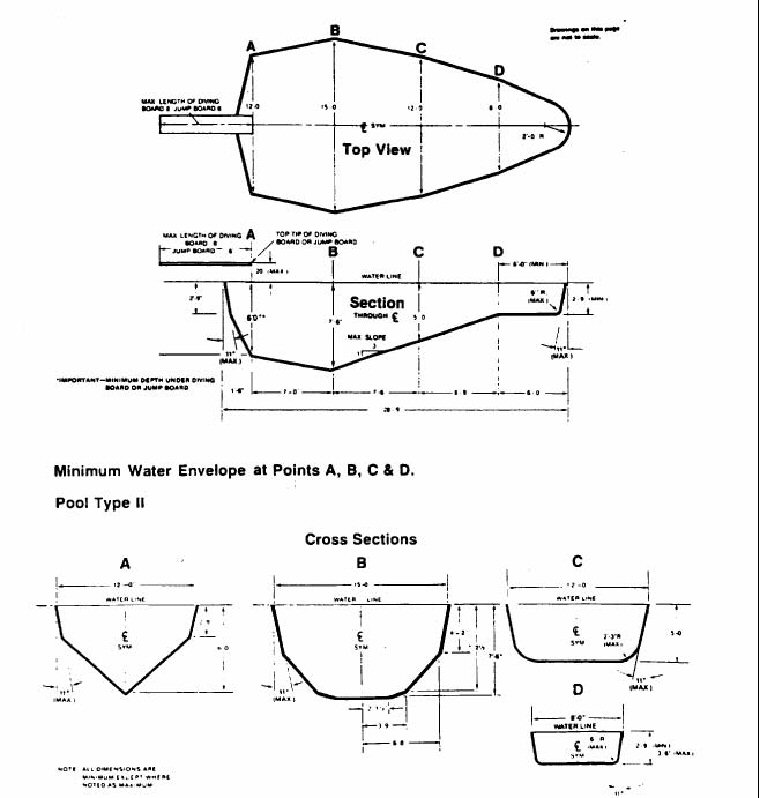
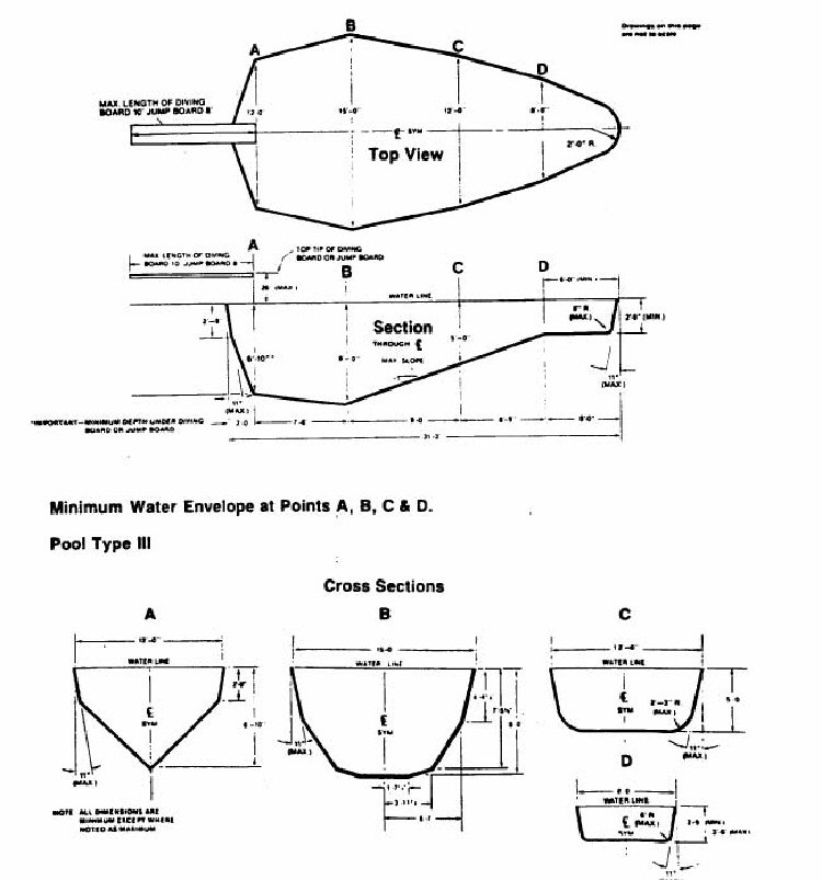
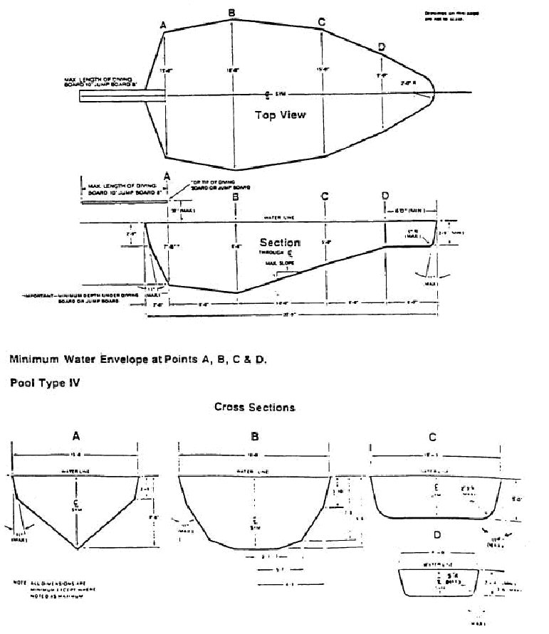
(3) S4210.3 The minimum allowable underwater cross sections at B, C, and D shall be as shown on drawings of Type I through Type V pools (section 4308.4 through 4308.5 of this rule, Figures No. 4-5 through 4-6).
(4) S4210.4 Constant depth and other swimming pools on which diving equipment is prohibited (Type O) with water depths not exceeding four (4) feet shall not be limited in width, length, or depth of water except as provided in sections 4 and 5 of this rule.
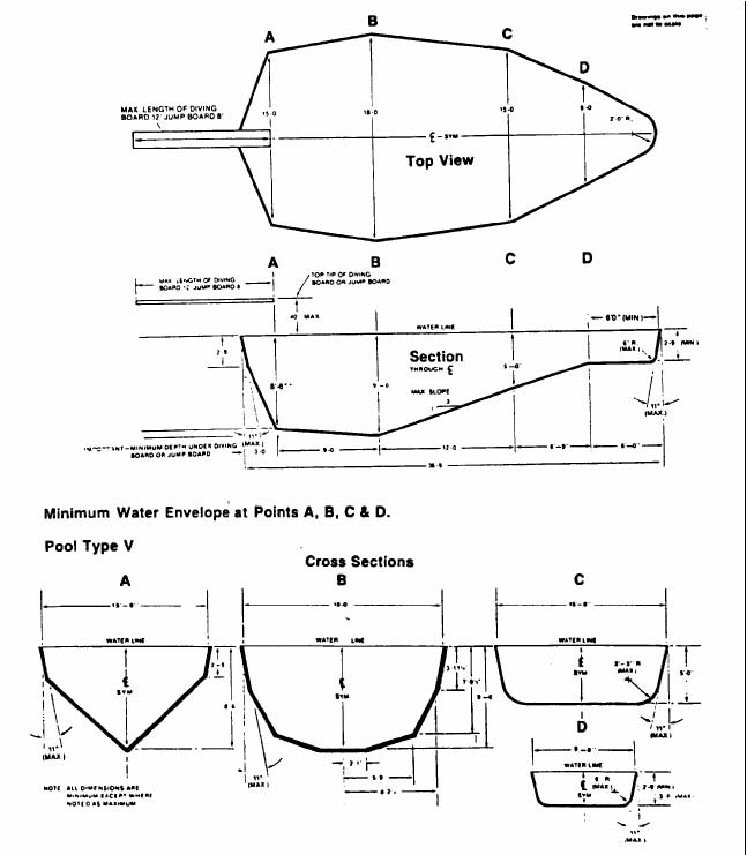
(5) S4210.5. Stationary diving platforms built on-site shall be located in the diving area of the pool so as to provide the minimum dimension as shown in Figure No. 4-1, at a maximum height of three (3) feet above the waterline. Point "A" shall be eighteen (18) inches in front of the wall at the platform center line. Stationary diving platforms shall not extend more than eighteen (18) inches horizontally over the water from the wall.
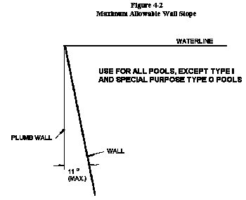
(6) S4210.6 This section contains Figure No. 4-2, a maximum allowable wall slope.
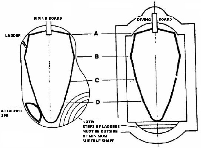
(7) S4210.7 This section contains Figure No. 4-3, relationship of minimum top view dimensions to steps or stairs.
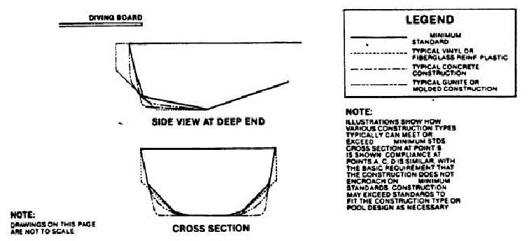
(8) S4210.8 This section contains Figure No. 4-4, relationship of vinyl, fiberglass, gunite, and concrete construction to minimum requirements.
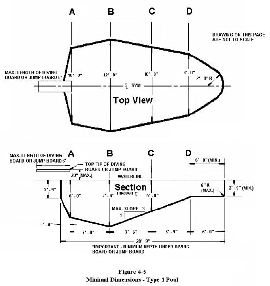
(9) S4210.9 This section contains Figure No. 4-5, minimum dimensions for a Type I pool.
(10) S4210.10 This section contains Figure No. 4-6, minimum dimensions for a Type II pool.
(11) S4210.11 This section contains Figure No. 4-7, minimum dimensions for a Type III pool.
(12) S4210.12 This section contains Figure No. 4-8, minimum dimensions for a Type IV pool.
(13) S4210.13 This section contains Figure No. 4-9, minimum dimensions for a Type V pool.
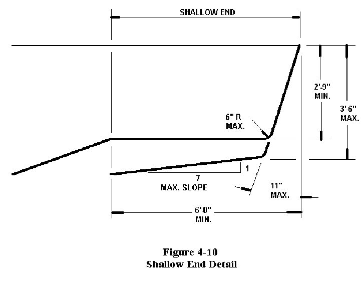
(14) S4210.14 This section contains Figure No. 4-10, shallow end detail for pool Types II through V.
SECTION 12. 675 IAC 14-4.3-280 IS ADDED TO READ AS FOLLOWS:
675 IAC 14-4.3-280 Offset ledges and underwater seat benches
Authority:
Sec. 280. Section S4211 Offset ledges and underwater seat benches is added as follows:
(Fire Prevention and Building Safety Commission;
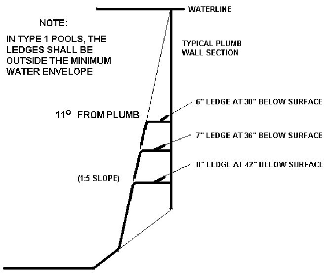
(1) S4211.1 Offset ledges, when provided, shall fall within eleven (11) degrees from plumb starting at the junction of the pool wall and waterline and shall have a slip-resisting surface. Maximum width shall be eight (8) inches. The typical allowable dimensions are based on the depths shown as follows:
(2) S4211.2 Underwater seat benches, where provided, shall:
(A) have a maximum horizontal seat bench depth of twenty (20) inches below the waterline;
(B) be visually set apart;
(C) have a slip-resisting surface; and
(D) be located fully outside of the required minimum diving water envelope if the pool is designed for use with manufactured diving equipment.
Underwater seat benches shall be permitted in the deep end of the pool only if they are either completely recessed, shaped to be compatible with the slope of the pool wall, or in a corner of the pool.
SECTION 13. 675 IAC 14-4.3-281 IS ADDED TO READ AS FOLLOWS:
675 IAC 14-4.3-281 Decks and deck equipment
Authority:
Sec. 281. Section S4212 Decks and deck equipment is added as follows:
(Fire Prevention and Building Safety Commission;
(1) S4212.1 Deck work shall be designed and installed so as to include the quality of subbase, concrete mix design, reinforcing, joints, and finishes. Work performed in accordance with the recommended practices of the American Concrete Institute (ACI) Standard 302.1R-80, "Guide for Concrete Floor and Slab Construction", may be deemed acceptable.
(2) S4212.2 Decks, ramps, coping, and similar step surfaces shall be slip-resisting and easily cleanable.
(3) S4212.3 Special features in or on decks such as markers, brand insignias, or similar features shall conform to this section.
(4) S4212.4 Steps outside the pool perimeter shall be in accordance with 675 IAC 14 , the Indiana One and Two Family Dwelling Code.
(5) S4212.5 Excavation areas shall be adequately compacted when they support the deck or decks.
(6) S4212.6 Decks shall be sloped to effectively drain either to perimeter areas or to deck drains. Drainage shall remove pool splash water, deck cleaning water, and rainwater without leaving standing water.
(7) S4212.7 The minimum slope of decks shall be:
(A) one-eighth (1/8) inch per one (1) foot (1/8:12) for textured, hand-finished concrete decks;
(B) one-fourth (1/4) inch per one (1) foot (1/4:12) for exposed aggregate concrete decks; and
(C) one-half (1/2) inch per one (1) foot (1/2:12) for indoor/outdoor carpeting decks.
(8) S4212.8 The maximum slope for all decks other than wood decks shall be one (1) inch per foot except for ramps. The maximum slope for wood decks shall be one-eighth (1/8) inch per foot except for ramps. Expansion gaps shall be based on good engineering practices with respect to the type of wood used.
(9) S4212.9 The maximum voids between adjoining concrete slabs and/or between concrete slabs and expansion joint material shall be three-sixteenths (3/16) inch of horizontal clearance with a maximum difference in vertical elevation of one-fourth (1/4) inch.
(10) S4212.10 Construction joints where pool coping meets concrete decks shall be watertight and shall not allow water to pass to the ground beneath.
(11) S4212.11 The areas where the decks join pool coping shall be designed and installed so as to protect the coping and its mortar bed from damage as a result of reasonable movement of adjoining decks.
(12) S4212.12 Joints in decks shall be provided to minimize the potential for cracks due to a change in elevations, separation of surfaces, or movement of the slab.
(13) S4212.13 The areas where decks join concrete work shall be protected by expansion joints to protect the pool adequately from the pressures of relative movements.
(14) S4212.14 Decks shall be edged, have a radius, or be otherwise relieved to eliminate sharp corners.
(15) S4212.15 Site drainage shall be provided so as to direct all perimeter deck drainage as well as general site and roof drainage away from the pool.
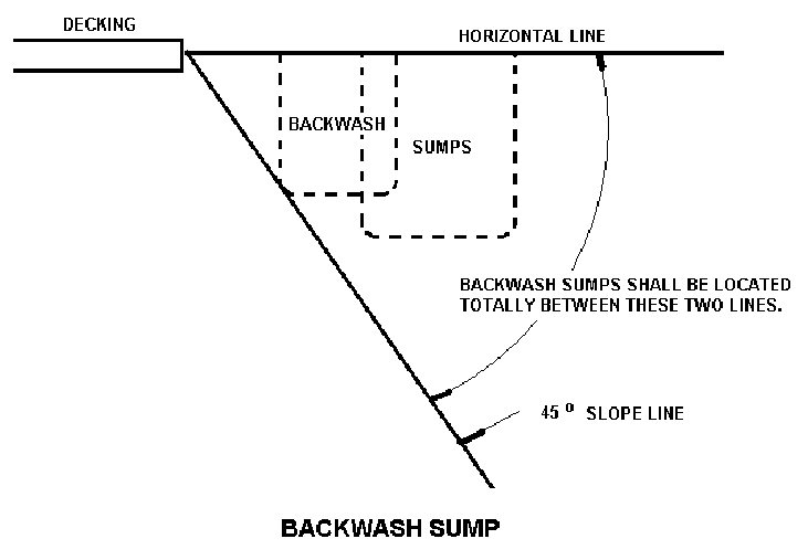
(16) S4212.16 If used, an open pit or leaching design for backwash sump purposes shall be located so that it falls completely below adjacent decks and fully outside a line projected forty-five (45) degrees downward and away from such decks as shown below.
SECTION 14. 675 IAC 14-4.3-282 IS ADDED TO READ AS FOLLOWS:
675 IAC 14-4.3-282 Circulation piping
Authority:
Sec. 282. Section S4213 Circulation piping is added as follows:
(Fire Prevention and Building Safety Commission;
(1) S4213.1 Circulation system piping, other than that integrally included in the manufacture of the pool, shall be subject to an induced static hydraulic pressure test (sealed system) at twenty-five (25) pounds per square inch for thirty (30) minutes. This test shall be performed before the deck is poured, and the pressure shall be maintained through the deck pour.
(2) S4213.2 Valves installed in or under any decks shall provide a minimum ten (10) inches diameter access cover and valve pit to facilitate servicing.
(3) S4213.3 A hose bibb with a vacuum breaker shall be provided for washing down the entire deck area.
SECTION 15. 675 IAC 14-4.3-283 IS ADDED TO READ AS FOLLOWS:
675 IAC 14-4.3-283 Pool egress
Authority:
Sec. 283. Section S4214 Pool egress is added as follows:
(Fire Prevention and Building Safety Commission;
(1) S4214.1 All pools shall have a means of entry/exit in the shallow end consisting of one (1) ladder, stairs, or recessed treads. Where two (2) or more entries/exits are used, the ladders, stairs, or recessed treads may be used in combination. All treads shall have slip-resisting surfaces.
(2) S4214.2 Where water depths are twenty-four (24) inches or less at the pool wall, the areas shall be considered as providing their own natural mode for entry/exit.
(3) S4214.3 For pools over thirty (30) feet in width, both sides of the deep portions of the pool shall have entries/exits provided.
(4) S4214.4 A means of entry/exit for the shallow end shall be located between the shallow end wall and the cross section at point "D". Where required, entry/exit for the deep end shall be between the deep end wall and the cross section at point "B". (Refer to section 9(b) of this rule, Figure No. 4-1.)
(5) S4214.5 Ladders, stairs, recessed treads, or underwater seat benches shall be provided at the deep end of the pool if the water depth is over five (5) feet.
(6) S4214.6 The design and construction of protruding and recessed pool stairs shall conform to the following:
(A) Step treads shall have a minimum unobstructed horizontal depth of ten (10) inches and a minimum unobstructed surface area of two hundred forty (240) square inches.
(B) Risers at the center line of the treads shall have a maximum uniform height of twelve (12) inches with the bottom riser height allowed to vary plus or minus two (2) inches from the uniform riser height.
(C) The vertical distance between the pool coping edge, deck, or step surface, which shall be slip-resisting, and the uppermost step tread shall be a maximum of twelve (12) inches.
(7) S4214.7 If handrails are used with stairs, they shall conform to the following:
(A) Handrails, if removable, shall be installed in such a way that they cannot be removed without the use of tools.
(B) The leading edge of handrails facilitating stairs and pool entry/exit shall be not more than eighteen (18) inches plus or minus three (3) inches horizontally from the vertical plane of the bottom riser, where applicable.
(C) The outside diameter of handrails shall be between one (1) inch and two (2) inches.
(8) S4214.8 Underwater seats or benches may be provided as part of the stairs or recessed treads.
(9) S4214.9 The design and construction of pool ladders shall conform to the following:
(A) Pool ladders shall be made entirely of corrosion-resisting materials.
(B) Ladders shall provide two (2) handholds or two (2) handrails.
(C) Below the water level, there shall be a clearance of not more than six (6) nor less than three (3) inches between any ladder tread edge measured from the pool wall side of the tread and the pool wall.
(D) The clear distance between ladder handrails shall be a minimum of seventeen (17) inches and a maximum of twenty-four (24) inches.
(E) There shall be a uniform height between ladder treads with a seven (7) inch minimum distance and a twelve (12) inch maximum distance.
(F) Ladder treads shall have a minimum horizontal depth of one and one-half (1 1/2) inches.
(G) The vertical distance between the top tread and the pool coping or deck shall be a maximum of twelve (12) inches.
(10) S4214.10 The design and construction of recessed treads in the pool wall shall conform to the following:
(A) Recessed treads at the center line shall have a uniform vertical spacing of twelve (12) inches maximum and seven (7) inches minimum.
(B) The vertical distance between the pool coping edge, deck, or step surface and the uppermost recessed tread shall be a maximum of twelve (12) inches.
(C) Recessed treads shall have a minimum depth of five (5) inches and a minimum width of twelve (12) inches.
(D) Recessed treads shall drain into the pool to prevent accumulation of dirt.
(E) Each set of recessed treads shall be provided with a pair of handrails/grab rails/handholds to serve all treads and risers.
SECTION 16. 675 IAC 14-4.3-284 IS ADDED TO READ AS FOLLOWS:
675 IAC 14-4.3-284 Diving equipment
Authority:
Sec. 284. Section S4215 Diving equipment is added as follows:
(Fire Prevention and Building Safety Commission;
(1) S4215.1 Supports, platforms, stairs, and ladders for manufactured diving equipment shall be designed to carry the anticipated loads. Stairs and ladders shall be of corrosion-resisting material, easily cleanable, and with slip-resisting tread. All manufactured diving stands higher than twenty-one (21) inches measured from the deck to the top butt end of the board shall be provided with stairs or a ladder, or both. Step treads shall be self-draining.
(2) S4215.2 Platforms and manufactured diving equipment of one (1) meter or higher shall be protected with guard rails, which shall be at least thirty (30) inches above the diving board and extend to the edge of the pool wall.
(3) S4215.3 Manufactured diving equipment shall be:
(A) designed for swimming pool use; and
(B) installed in accordance with the manufacturer's recommendations provided with the equipment.
(4) S4215.4 A label shall be permanently affixed to the manufactured diving equipment or jump board and shall include not less than:
(A) manufacturer's name and address;
(B) board equipment length;
(C) identification as to diving or jump board;
(D) fulcrum setting specifications, if applicable;
(E) date of manufacture; and
(F) reference to manufacturer's safety standard, if any, that the board will meet.
(5) 4215.5 Manufactured diving equipment suitable for installation on a lower pool type may be installed on any higher pool type providing no less a water envelope is provided from the tip of the board than called for in the lower type. Manufactured diving equipment of a greater type, for example, Type III, shall not be installed on a pool of lesser type, for example, Type II. In addition, the following provisions apply:
(A) Manufactured diving equipment shall have slip-resisting tread surfaces.
(B) Manufactured diving equipment shall be permanently anchored to the pool deck. The edge of the board at the tip end shall be level with the water surface. The tip end of the board over the pool water surface may be higher than the butt end of the board. Refer to manufacturer's recommendations.
SECTION 17. 675 IAC 14-4.3-285 IS ADDED TO READ AS FOLLOWS:
675 IAC 14-4.3-285 Swimming pool slides
Authority:
Sec. 285. Section S4216 Swimming pool slides is added as follows:
(Fire Prevention and Building Safety Commission;
(1) S4216.1 The requirements of the U.S. Consumer Product Safety Commission (CPSC) Standard for Swimming Pool Slides as published in 16 CFR 1207, shall be used for standards relating to swimming pool slides. Slides, where provided for use with swimming pools, shall have a permanent label or separate certificate indicating conformance with the rules of the Consumer Product Safety Commission issued as 16 CFR Ch. II, Part 1207.
(2) S4216.2 Swimming pool slides in residential swimming pools shall terminate such that the following applies:
(A) The end of the slide is not more than twelve (12) inches above the pool deck.
(B) The depth of the water at the end of the slide meets the manufacturer's recommendations or thirty-six (36) inches, whichever is greater.
(C) The distance from the end of the slide is not less than twenty (20) feet measured along the axis of travel.
(D) The depth of water described in clause (B) or a gradually increasing depth shall be maintained for not less than ten (10) feet beyond the end of the slide. This depth of water may gradually decrease beyond that point to a minimum water depth of twenty-four (24) inches. For this requirement a maximum slope of one (1) in seven (7) (1:7) shall be considered "gradual".
(3) S4216.3 Swimming pool slides shall be installed in accordance with the manufacturer's installation instructions and specifications.
SECTION 18. 675 IAC 14-4.3-286 IS ADDED TO READ AS FOLLOWS:
675 IAC 14-4.3-286 Circulation system
Authority:
Sec. 286. Section S4217 Circulation system is added as follows:
(Fire Prevention and Building Safety Commission;
(1) S4217.1 A circulation system consisting of pumps, piping, return inlets and suction outlets, filters, and other necessary equipment shall be provided for complete circulation of water through all parts of the pool. This circulation system shall be capable of maintaining water clarity and chemistry requirements.
(2) S4217.2 The equipment shall be of adequate size to turn over the entire pool water capacity at least once every twelve (12) hours. Water clarity shall be maintained. When standing at the pool's edge at the deep end, the deepest portion of the pool floor shall be visible.
(3) S4217.3 Circulation system components that require replacement or servicing shall be:
(A) accessible for inspection, repair, or replacement; and
(B) installed according to the manufacturer's instructions.
(4) S4217.4 Pool equipment shall be:
(A) properly supported to prevent damage from misalignment, settlement, etc.; and
(B) mounted so as to minimize the potential for the accumulation of debris and moisture following manufacturer's instructions.
(5) S4217.5 The water velocity in the pool piping shall not exceed ten (10) feet per second for discharge piping and eight (8) feet per second for suction piping, unless summary calculations are provided to show that the greater flow is possible with the pump and piping provided. In copper pipes, the velocity shall not exceed eight (8) feet per second for suction and discharge piping. Pool piping shall be sized to permit the rated flows for filtering.
(6) S4217.6 The circulation system piping and fittings shall be:
(A) nontoxic;
(B) considered to be process piping; and
(C) of material able to withstand operating pressures and operating conditions.
(7) S4217.7 Equipment shall be designed and fabricated to drain the pool water from the equipment, together with exposed face piping, by removal of drain plugs and manipulating valves, or by other methods. Refer to manufacturer's recommendations for specific information on draining the system.
(8) S4217.8 A pressure or vacuum gauge or other means of indicating system condition shall be provided in the circulation system in an easily readable location.
(9) S4217.9 Time clocks may be used to set the operating period of the circulation system. When time clocks are used, they shall also govern the operating time of appurtenant devices such as chemical/disinfectant feeders, slurry feeders, heaters, etc., that are dependent upon circulation pump flow.
(10) S4217.10 Written operation and maintenance instructions shall be provided for the circulation system.
SECTION 19. 675 IAC 14-4.3-287 IS ADDED TO READ AS FOLLOWS:
675 IAC 14-4.3-287 Filters
Authority:
Sec. 287. Section S4218 Filters is added as follows:
(Fire Prevention and Building Safety Commission;
(1) S4218.1 Filters shall be designed so that after cleaning per manufacturer's instructions the system can provide the water clarity noted in section S4217.1 of this rule.
(2) S4218.2 Filters shall be designed so that filtration surfaces can be inspected and serviced.
(3) S4218.3 On pressure-type filters, a means shall be provided to permit the release of internal pressure.
(4) S4218.4 Any filter incorporating an automatic internal air release as its principal means of air release shall have lids which provide a slow and safe release of pressure as a part of its design.
(5) S4218.5 Any separation tank used in conjunction with any filter tank shall have a manual means of air release or a lid that provides a slow and safe release of pressure as it is opened as a part of its design.
(6) S4218.6 Pressure filters and separation tanks shall:
(A) have operation and maintenance instructions permanently installed on the filter or separation tank; and
(B) include a precautionary statement warning not to start up the system after maintenance without first opening the air release and proper reassembly of the filter and separation tank.
The statement shall be visible and noticeable within the area of the air release.
(7) S4218.7 Piping furnished with the filter shall be of suitable material capable of withstanding one and one-half (1 1/2) times the working pressure. The suction piping shall not collapse when there is a complete shutoff of flow on the suction side of the pump.
SECTION 20. 675 IAC 14-4.3-288 IS ADDED TO READ AS FOLLOWS:
675 IAC 14-4.3-288 Pumps
Authority:
Sec. 288. Section S4219 Pumps is added as follows:
(Fire Prevention and Building Safety Commission;
(1) S4219.1 A pump and motor shall be provided for circulation of the pool water. Performance of all pumps shall meet or exceed the conditions of flow required for filtering, cleaning, if applicable, and the filters against the total dynamic head developed by the complete system.
(2) S4219.2 With all pressure filter systems a cleanable strainer or screen shall be provided upstream of the circulation pumps to remove solids, debris, hair, lint, etc.
(3) S4219.3 Pumps and motors shall be accessible for inspection and service.
(4) S4219.4 The design and construction of the pumps and component parts shall provide safe operation that is not hazardous to the operator or maintenance personnel.
(5) S4219.5 Where a mechanical pump seal is provided, components of the seal shall be corrosion-resisting and capable of operating under conditions normally encountered in pool operation.
(6) S4219.6 Proper direction of rotation for the pump shall be clearly indicated on the pump.
(7) S4219.7 All motors shall:
(A) have as a minimum an open drip-proof enclosure; and
(B) be constructed electrically and mechanically to perform satisfactorily and safely under the conditions of load and environment normally encountered in swimming pool installations.
(8) S4219.8 Motors shall be capable of operating the pumps under full load with a voltage variation of plus or minus ten percent (10%) from the nameplate rating. If the maximum service factor of the motor is exceeded (at full voltage), the manufacturer shall indicate this on the pump curve.
(9) S4219.9 All motors shall have thermal or current overload protection, either built-in or in the line starter, to provide locked rotor and running protection.
(10) S4219.10 Where the pump is below the waterline, valves shall be installed on permanently connected suction and discharge lines, located in an accessible place outside the walls of the pool, where they shall be readily and easily accessible for maintenance and removal of the pump.
SECTION 21. 675 IAC 14-4.3-289 IS ADDED TO READ AS FOLLOWS:
675 IAC 14-4.3-289 Return inlets and suction outlets
Authority:
Sec. 289. Section S4220 Return inlets and suction outlets is added as follows:
(Fire Prevention and Building Safety Commission;
(1) S4220.1 Return inlets and suction outlets shall be provided and arranged to produce a uniform circulation of water and maintain a uniform disinfectant residual throughout the entire pool. Where skimmers are used, the return inlets shall be located so as to help bring floating particles within range of the skimmers.
(2) S4220.2 The number of return inlets shall be based on a minimum of one (1) return inlet per six hundred (600) square feet of pool surface area, or fraction thereof. Return inlet fittings shall be installed of sufficient pipe size or quantity to allow a full design turnover rate of the circulation system in accordance with the manufacturer's recommendations for return inlets.
(3) S4220.3 Return inlets from the circulation system shall be designed so as not to constitute a hazard to the bather.
(4) S4220.4 The pool shall not be operated if the suction outlet grate is missing, broken, or secured in such a way that it can be removed without the use of tools.
(5) S4220.5 If the suction outlet system, such as a filtration system, booster system, automatic cleaning system, solar system, etc., has a single suction outlet, or multiple suction outlets that can be isolated by valves, each suction outlet shall protect against bather entrapment by:
(A) an antivortex cover;
(B) a twelve (12) inch by twelve (12) inch (12 × 12) grate or larger; or
(C) other means acceptable to the local authority.
(6) S4220.6 Where provided, the vacuum cleaner fittings shall be located in accessible positions at least six (6) inches and not greater than eighteen (18) inches below the minimum operating water level or as an attachment to the skimmers.
SECTION 22. 675 IAC 14-4.3-290 IS ADDED TO READ AS FOLLOWS:
675 IAC 14-4.3-290 Surface skimmer systems
Authority:
Sec. 290. Section S4220 Surface skimmer systems is added as follows:
(Fire Prevention and Building Safety Commission;
(1) S4220.1 A surface skimming system shall be:
(A) provided on all residential swimming pools; and
(B) designed and constructed to skim the pool surface when the water level is maintained within the operational parameters of the system's rim or weir device.
(2) S4220.2 Skimming devices shall be designed and installed so as not to constitute a hazard to the bather.
(3) S4220.3 Where automatic surface skimmers are used as the sole overflow system, at least one (1) surface skimmer shall be provided for each eight hundred (800) square feet or fraction thereof of the water surface area. Nominal recessed areas such as stairs, spas, etc., shall not be considered in the calculation. Where skimmers are used, they shall be located to maintain effective skimming action over the entire surface of the pool.
SECTION 23. 675 IAC 14-4.3-291 IS ADDED TO READ AS FOLLOWS:
675 IAC 14-4.3-291 Electrical requirements
Authority:
Sec. 291. Section E4221 Electrical requirements is added as follows: E4221.1 The requirements of 675 IAC 17 , the Indiana Electrical Code, shall be followed in the installation of all electrical equipment wiring or appliances in the pool area or vicinity of the pool's circulation system.
(Fire Prevention and Building Safety Commission;
SECTION 24. 675 IAC 14-4.3-292 IS ADDED TO READ AS FOLLOWS:
675 IAC 14-4.3-292 Heaters
Authority:
Sec. 292. Section E4222 Heaters is added as follows:
(Fire Prevention and Building Safety Commission;
(1) E4222.1 Swimming pool heaters shall be of an "approved" type.
(2) E4222.2 Heaters shall be properly sized.
(3) E4222.3 The heaters shall be installed according to the manufacturer's recommendations, but not less than the following:
(A) The heater shall be installed on a concrete (or equivalent) base unless it is specifically designed for installation on a combustible surface.
(B) When installing the heater, adequate clearances shall be maintained on all sides and over the top of the unit. Consult manufacturer's instructions for proper clearances.
(C) In order to assure proper combustion, the heater shall have adequate ventilation installed as follows:
(i) When installing a heater indoors, proper openings to the room are required. The heater shall be installed in accordance with 675 IAC 18 , the Indiana Mechanical Code, and the manufacturer's recommendations for properly sized air openings to the enclosure.
(ii) All fossil fuel heaters shall be supplied with some type of venting system for either indoor or outdoor installation. These draft or venting devices shall be installed according to the manufacturer's recommendations and shall not be modified.
(iii) When installing a heater that will be using propane gas, special precautions shall be noted. Propane gas is heavier than air and, therefore, can create special problems when the heater is installed in a pit or in an enclosed area. Whenever installing a heater with propane gas, the manufacturer's ventilation recommendations shall be followed.
(4) E4222.4 The heater gas supply and pipe sizing shall:
(A) be adequate; and
(B) comply with manufacturer's recommendations.
When installing a gas-fired heater, the gas line shall be run from the gas meter as directly as practical.
(5) E4222.5 The heater circulation system shall comply with the manufacturer's recommendations. Precautions shall be taken to avoid siphonage of hot water into the pump or filter. When manufacturers recommend metal pipe, that is, copper, heat sinks, they shall be installed vertically connected to the heater to prevent heat damage to plastic circulation pipe. Heater piping shall be designed to avoid excessive friction losses through the pipe or bypass valves, or both, required. When installing bypass valves, caution shall be taken to ensure adequate flow through the heater at all times.
(6) E4222.6 The water piping system shall be installed according to the manufacturer's recommendations. When manufacturers recommend precautions to eliminate siphonage so that the heater does not destroy the filter or any plastic pipe that is being used, the manufacturer's recommendations shall be followed. NOTE: When installing a heater and a filter system, adequate provisions shall be made so that the heater does not cause excessive pressure drop to the filter system. Refer to manufacturer's requirements or recommendations, or both, for installation of bypass valves. Excessive flow that causes pressure drop can be eliminated by the installation of an external or an automatic bypass valve. When installing a bypass valve, caution shall be noted so that there is always adequate flow through the heater.
(7) E4222.7 A time clock is recommended, and when used it shall be set long enough to properly filter the water and allow enough time for proper heating of the pool. It is recommended that a dual time clock or fireman's switch be used in conjunction with the heater to shut the heater off approximately one-half (1/2) hour before the filter system shuts down.
SECTION 25. 675 IAC 14-4.3-293 IS ADDED TO READ AS FOLLOWS:
675 IAC 14-4.3-293 Water supply
Authority:
Sec. 293. Section S4223 Water supply is added as follows:
(Fire Prevention and Building Safety Commission;
(1) S4223.1 The water supply serving the pool, which may come from a variety of sources, shall meet 327 IAC, the rules of the water pollution control board, before the bather uses the pool.
(2) S4223.2 No direct mechanical connection shall be made between the potable water supply and the swimming pool, chlorinating equipment, or the system of piping for the pool unless it is protected against backflow and siphonage in a manner approved by 675 IAC 16 , the Indiana Plumbing Code, or through an air gap meeting that same code.
(3) S4223.3 An over-the-rim spout, if used, shall be located under a diving board, adjacent to a ladder, or otherwise properly shielded so as not to create a hazard. Its open end shall:
(A) have no sharp edges; and
(B) not protrude more than two (2) inches beyond the edge of the pool.
SECTION 26. 675 IAC 14-4.3-294 IS ADDED TO READ AS FOLLOWS:
675 IAC 14-4.3-294 Wastewater disposal
Authority:
Sec. 294. Section S4224 Wastewater disposal is added as follows: S4224.1 Backwash water shall be discharged into a sanitary sewer through an approved air gap or into an approved subsurface disposal system or by other means in accordance with 675 IAC 16 , the Indiana Plumbing Code, and 327 IAC, the rules of the water pollution control board.
(Fire Prevention and Building Safety Commission;
SECTION 27. 675 IAC 14-4.3-295 IS ADDED TO READ AS FOLLOWS:
675 IAC 14-4.3-295 Disinfectant; oxidation; chemical feeder equipment
Authority:
Sec. 295. Section S4225 Disinfectant; oxidation; chemical feeder equipment is added as follows:
(Fire Prevention and Building Safety Commission;
(1) S4225.1 Disinfectant equipment, oxidation equipment, and chemical feeders, hereafter referred to jointly as "equipment", shall be capable of precisely introducing a sufficient quantity of an approved disinfecting agent or other chemical to maintain one (1) milligram per liter of free chlorine residual.
(2) S4225.2 Manufacturer's instructions shall be used in installing chemical feeders. The installation and use of chemical feeders shall conform to the following:
(A) Where using chemical feeders, it is extremely important that they be installed downstream from the filter and heater. An exception is equipment specifically labeled for feeding to the suction side of the pump.
(B) If the chemical feeder is equipped with its own pump, it shall be installed so it introduces the gas or solution downstream from the heater and, if possible, at a position lower than the heater outlet fitting.
(C) Chemical feed pumps shall be wired so they cannot operate unless the filter pump is running. If the chlorinator has an independent timer, the filter and chemical feed pump timers shall be interlocked.
(D) A check valve shall be installed in the piping between the heater and the point of chemical feed.
(3) S4225.3 The installation of ozone generating equipment shall be limited to low ozone output generating equipment. The installation and use of ozone generating equipment shall conform to the following:
(A) Installation of ozone generating equipment shall allow for indications of operation or malfunction to be easily observed. The equipment shall be installed in a manner such that a malfunction will not endanger operators or pool users.
(B) Ozone generating equipment shall be used in conjunction with other chemical treatments to meet the chemical operating parameters in this section. Normal maintenance and monitoring of water chemistry shall be followed.
(C) If the equipment is capable of exposing maintenance or service personnel to ozone concentrations exceeding five hundred (500) parts per million, a self-contained breathing apparatus approved for ozone usage shall be provided. If a distinct, pungent odor is smelled when the ozone generating equipment is operating, the equipment shall be shut down, and the area shall be ventilated. The equipment shall be inspected and repaired as necessary by qualified service personnel.
(D) Manufacturer's recommendations shall be used to determine where and how ozone shall be injected.
SECTION 28. 675 IAC 14-4.3-296 IS ADDED TO READ AS FOLLOWS:
675 IAC 14-4.3-296 Safety features
Authority:
Sec. 296. Section S4226 Safety features is added as follows:
(Fire Prevention and Building Safety Commission;
(1) S4226.1 A residential pool shall be provided with a suitable handhold around its perimeter in areas where depths exceed three (3) feet six (6) inches. Handholds shall be provided no further apart than four (4) feet and shall consist of any one (1) or a combination of items listed as follows:
(A) Coping, ledge, or deck along the immediate top edge of the pool that provides a slip-resisting surface of at least four (4) inches minimum horizontal width and located at or not more than twelve (12) inches above the waterline.
(B) Ladders, stairs, or seat ledges.
(C) A secured rope or railing placed at or not more than twelve (12) inches above the waterline.
(2) S4226.2 Rope anchor devices shall be installed at a minimum of one (1) foot and a maximum of two (2) feet on the shallow end side of a point of change in floor slope. In pools where the slope change occurs in water depths less than four (4) feet six (6) inches, a transition rope supported by buoys shall be installed.
(3) S4226.3 Access to residential pools shall be restricted by one (1) of the following means:
(A) Walls or fencing not less than four (4) feet high and completely surrounding the pool and deck area with the exception of self-closing and latching gates and doors, both capable of being locked.
(B) Other means not less than four (4) feet high and deemed impenetrable by the enforcing authority at the time of construction and completely surrounding the pool and deck area when the pool is not in use.
(C) A combination of clauses (A) and (B) that completely surrounds the pool and deck with the exception of self-closing and latching gates and doors which are capable of being locked. This applies to clauses (A) and (B) and this clause only.
(D) A power safety pool cover that:
(i) shall provide a continuous connection between the cover and the deck, so as to prohibit access to the pool when the cover is completely drawn over the pool;
(ii) shall be mechanically operated by a key or key and switch such that the cover cannot be drawn open or retracted without the use of a key;
(iii) is installed with track, rollers, rails, guides, or other accessories necessary to accomplish items (i) and (ii), in accordance with the manufacturer's instructions; and
(iv) shall bear an identification tag indicating that the cover satisfies the requirements of ASTM F 1346-91 (2003) for power safety pool covers.
(4) S4226.4 Not less than the following lifesaving equipment shall be installed with each residential swimming pool:
(A) A ring or throwing buoy fitted with forty (40) feet of one-fourth (1/4) inch diameter line.
(B) A pole not less than twelve (12) feet in length.
(C) Access to a telephone.
SECTION 29. 675 IAC 20-1.1-1 IS AMENDED TO READ AS FOLLOWS:
675 IAC 20-1.1-1 Title and availability
Authority: Sec. 1. (a) This article shall be known as the Indiana Swimming Pool, Spa and Water Attraction Code, second third edition. and will be published by the Indiana fire and building services department for general use and distribution under that title. Whenever the term "this code" is used in this article, it shall mean the Indiana Swimming Pool, Spa and Water Attraction Code, second third edition.
(b) The Indiana Swimming Pool, Spa and Water Attraction Code is available for purchase from the Indiana Fire and Building Services Department, 1099 North Meridian Street, Suite 900, at the Department of Homeland Security, Code Services Section, Indiana Government Center South, 302 West Washington Street, Room W246, Indianapolis, Indiana 46204.
(Fire Prevention and Building Safety Commission;
SECTION 30. 675 IAC 20-1.1-3 IS AMENDED TO READ AS FOLLOWS:
675 IAC 20-1.1-3 Definitions "A"
Authority: Sec. 3. (a) "Abrasion hazard" means a sharp or rough surface which that could cause injury under normal use.
(b) "Accessible" means, when applied to a fixture, connection, appliance, or equipment, having access thereto, but may require the removal of an access panel, door, or similar obstruction. "Readily accessible" means direct access without the necessity of removing any panel, door, or similar obstruction.
(c) "Agitation" means the mechanical or manual movement to dislodge the filter aid and dirt from the filter element.
(d) "Airbreak" means a physical separation which that may be a low inlet into the indirect waste receptor from the fixture, appliance, or device indirectly connected.
(e) "Air bump assist backwash" means, in a diatomite type filter, the compressing of a volume of air in the filter effluent chamber (by means of an air compressor or by the water pressure from the recirculating pump) which, that, when released, rapidly decompresses and forces water in the filter tank through the elements in a reverse direction dislodging the filter aid and accumulated dirt and carrying them to waste.
(g) "Air induction system" means a system whereby a volume of air (only) is induced into hollow ducts built into a spa floor, bench, or other location. The air induction system is activated by a separate air power unit (blower).
(h) "Approved" means, as to materials, equipment, design, and types of construction, the approval by the state building commissioner as the result of acceptance by the code official by one (1) of the following methods:
(1) Investigation and or tests conducted by him or by reason of recognized authorities.
(2) Investigation or tests conducted by technical or scientific organizations.
(3) Accepted principles. or tests by approved agencies.
The investigation, tests, or principles shall establish that the materials, equipment, and types of construction are safe for the intended purpose.
(i) "Approved agency" means an established and recognized agency regularly engaged in conducting tests or furnishing inspection services, when such the agency has been approved by the state building commissioner or is listed in 675 IAC 12-6-11 .
(Fire Prevention and Building Safety Commission;
SECTION 31. 675 IAC 20-1.1-4 IS AMENDED TO READ AS FOLLOWS:
675 IAC 20-1.1-4 Definitions "B"
Authority: Sec. 4. (a) "Backwash" means the process of thoroughly cleaning the filter medium and/or or elements, or both, by the reverse flow of water.
(b) "Backwash cycle" means the time required to backwash the filter system thoroughly.
(c) "Backwash pipe" means a type of filter waste discharge piping as defined in section 8(o) of this rule.
(d) "Backwash rate" means the rate of application of water through a filter during the backwash cycle expressed in United States gallons per minute per square foot (liters per minute per square meter) of effective filter area.
(e) "Basin" means any vessel:
(1) constructed of man-made materials; and
(2) designed to hold water to be used as a swimming pool, spa, or water attraction.
SECTION 32. 675 IAC 20-1.1-5 IS AMENDED TO READ AS FOLLOWS:
675 IAC 20-1.1-5 Definitions "C"
Authority: Sec. 5. (a) "Cartridge" means a filter component of either the depth or surface type having fixed dimensions and designed to remove suspended particles from water flowing through the unit.
(b) "Cartridge, depth type" means a filter cartridge with a medium relying on penetration of particulates into the medium for removal and providing adequate holding capacity of such particulates.
(c) "Cartridge, surface type" means a filter cartridge with a medium relying on retention of particles on the surface of the cartridge for removal.
(d) "Chemical feeder" means any device used to feed chemicals such as sanitizers, pH adjusters, algicide, etc. into a pool or spa.
(e) "Chemical feeder output rate" means the weight or volume of active ingredients delivered by a chemical feeder expressed in units of weight of volume and time.
(f) "Chemical feed rate indicator" means a mechanism which that will produce reproducible results expressed in units of weight or volume of chemical per unit of time or per unit of volume of water. said The mechanism may:
(1) be a direct reading instrument; or may
(2) require the use of a reference chart.
(g) "Chemical piping" means piping which that conveys concentrated chemical solutions from a feeding apparatus to the circulation piping.
(h) "Circulation piping system" means the piping between the pool structure and the mechanical equipment. It usually includes suction piping, face piping, and return piping. an arrangement of mechanical equipment or components, or both, designed to ensure even distribution of heat, chemicals, and filtrated water throughout the pool or spa. The term includes filters, pumps, strainers, disinfectant, or other chemical feed devices, piping, inlets, drains, overflow fittings, and other appurtenances.
(i) "Code official" means the division of fire and building safety, the local building official as authorized under IC 36-7-2-9 and local ordinance, or the fire department as authorized under IC 36-8-17-9 .
SECTION 33. 675 IAC 20-1.1-8 IS AMENDED TO READ AS FOLLOWS:
675 IAC 20-1.1-8 Definitions "F"
Authority: Sec. 8. (a) "Face piping" means the piping, with all valves and fittings, which that is used to connect the filter system together as a unit.
(b) "Family pool" means a residential swimming pool.
(c) "Filter" means a device that separates solid particles from water by circulating the water through a porous substance (a filter medium element).
(e) "Filter, cartridge" means a filter that uses a porous cartridge as its filter medium.
(g) "Filter, diatomaceous earth" means a filter that uses a thin layer of diatomaceous earth as its filter medium that periodically must be replaced.
(j) "Filter, permanent medium" means a filter that under normal use will not have to be replaced.
(k) "Filter rate" means the rate of application of water to a filter expressed in gallons per minute per square foot of effective filter area.
(l) "Filter rock" means graded, rounded rock and/or or gravel, or both, not subject to degradation by common pool chemical used to support filter media.
(m) "Filter sand" means a specially graded type of permanent filter media.
(n) "Filter septum" means that part of the filter element in a diatomite type filter upon which a cake of diatomite or other nonpermanent filter aid may be deposited.
(o) "Filter waste discharge piping" means piping that conducts wastewater from a filter to a drainage system. Connection to drainage system is made through an airgap or other approved method.
(q) "Flow balance valve" means a device to regulate the effluent from the skimmer housing of each of a combination of two (2) or more surface skimmers.
(r) "Freeboard" means the clear vertical distance in a sand type filter between the top of the filter media and the lowest outlet of the upper distribution system.
(s) "Fresh water" means water having a specific conductivity less than a solution containing six thousand (6,000) parts per million of sodium chloride.
(t) "Friction loss" means the pressure drop expressed in feet (meters) of water or psi (Pascals) caused by liquid flowing through the piping and fittings.
(Fire Prevention and Building Safety Commission;
SECTION 34. 675 IAC 20-1.1-10 IS AMENDED TO READ AS FOLLOWS:
675 IAC 20-1.1-10 Definitions "I"
Authority: Sec. 10. (a) "Indirect waste pipe" means a pipe that does not connect directly with the drainage system but conveys liquid wastes by discharging into a plumbing fixture, interceptor, or receptacle which that is directly connected to the drainage system.
(b) "Inlet fitting" means a fitting or fixture through which circulated or hydrojetted water enters a pool, spa, or hot tub.
(c) "Interactive play attraction" means a water attraction, including, but not limited to, manufactured devices using sprayed, jetted, or other water sources contacting the users and not incorporating a basin and standing or captured water as part of the user activity area, such as splash pads and spray pads.
(Fire Prevention and Building Safety Commission;
SECTION 35. 675 IAC 20-1.1-11 IS AMENDED TO READ AS FOLLOWS:
675 IAC 20-1.1-11 Definitions "J"
Authority: Sec. 11. (a) "Jump board" means a recreational mechanism that has a coil spring, leaf spring, or comparable device located beneath the board which that is activated by the force exerted in jumping on the board.
SECTION 36. 675 IAC 20-1.1-12 IS AMENDED TO READ AS FOLLOWS:
675 IAC 20-1.1-12 Definitions "L"
Authority: Sec. 12. (a) "Ladders" mean the following:
(4) "Portable ladder" means a ladder that is intended to be removed easily when a pool is not in use.
(1) "Deck ladder" means a ladder for deck access from outside the pool.
(2) "In-pool ladder" means a ladder located in a pool to provide ingress and egress from the deck.
(3) "Limited access ladder" means a ladder with provision for making entry inaccessible when a pool is not in use, i.e., that is, swing-up, slide-up, or equivalent.
(b) "Light reflectance value" or "LRV" means a scientifically determined numerical rating on the amount of light and heat that a color will reflect on a scale of zero (0) to one hundred (100). Pure black is zero (0), and pure white is nearly one hundred (100).
(1) "Expandable liner" means a liner that is constructed of a material that has the capability of stretching into a greater depth of irregular shape other than the original constructed dimensions.
(2) "Hooper "Hopper liner" means a liner that is used to obtain greater depth by geometrical pattern construction on the liner bottom or floor to fit a predetermined size and shape.
(1) meets appropriate standards; or
(2) has been tested and found suitable for use in a specified manner.
(1) collect the water during the filtering; and to
(2) distribute the water during the backwashing.
SECTION 37. 675 IAC 20-1.1-13 IS AMENDED TO READ AS FOLLOWS:
675 IAC 20-1.1-13 Definitions "M"
Authority: Sec. 13. (a) "Main outlet" means the outlet fitting or fittings directly connected to a pump suction and located at or near the bottom deepest portion of a swimming pool, spa, or hot tub through which passes water passes to the recirculating pump. system. This outlet is often erroneously referred to as the "main drain" or "suction outlet".
(b) "Make-up water" means fresh water used to fill or refill the pool.
(c) "Multiport valve" means a valve for various filter operations, which combines in one (1) unit the function of two (2) or more single direct flow valves.
(Fire Prevention and Building Safety Commission;
SECTION 38. 675 IAC 20-1.1-15 IS AMENDED TO READ AS FOLLOWS:
675 IAC 20-1.1-15 Definitions "O"
Authority: Sec. 15. (a) "Overflow system" means perimeter type overflows, surface skimmers, and surface water collection systems of various design and manufacture.
(b) "Ozone treatment" means the oxidation of water contaminants using a device that exposes air or oxygen to corona discharge.
(Fire Prevention and Building Safety Commission;
SECTION 39. 675 IAC 20-1.1-16 IS AMENDED TO READ AS FOLLOWS:
675 IAC 20-1.1-16 Definitions "P"
Authority: Sec. 16. (a) "Perimeter overflow system" means a continuous channel formed into the sidewall entirely around the perimeter of the pool, unless interrupted by steps, into which surface pool water is continuously drawn during normal operation to provide a skimming action.
(b) "Pinching hazard" means any configuration of components that would pinch or entrap the fingers or toes of a bather.
(c) "Play feature" means a physical object installed in or adjacent to a pool or water attraction that is intended for recreational use.
(1) "Activity pool" means a water attraction with a depth of greater than twenty-four (24) inches designed primarily for play activity that uses constructed features and devices including, but not limited to, pad walks, flotation devices, and similar attractions. The installation of a single basketball hoop, flotation device, or volleyball net does not transform a pool into a water attraction.
(2) "Combination pool" means a pool used for swimming and diving.
(3) "Diving pool" means a pool used exclusively for diving.
(4) "Exercise pool" means a pool of shallow depth usually associated with a health spa and that may or may not have a current.
(5) "Limited purpose pool" means a pool used for a purpose not otherwise defined, such as for:
(A) apparatus swimming;
(B) underwater photography training; or
(C) another special use by the public.
(6) "Mobile pool" means a pool constructed on a mobile structure that is capable of being transported from place to place.
(7) "Plunge pool" means a pool:
(A) with a depth of greater than twenty-four (24) inches;
(B) located at the exit end of a waterslide flume; and
(C) intended and designed to receive slide users emerging from the flume.
(8) "Special use pool" means a pool intended to be used as a water attraction or in conjunction with a water attraction.
(9) "Swimming pool" has the meaning set forth in section 18(u) of this rule.
(10) "Therapy pool" means a pool used exclusively for medically administered therapy.
(11) "Vanishing edge pool" means a pool where the top of one (1) or more of the basin wall or walls is submerged with no adjacent deck or decks.
(12) "Vortex pool" means a circular pool that is equipped with a method of transporting water in the pool for the purpose of propelling users at speeds dictated by the velocity of the moving stream.
(13) "Wading pool" means a shallow pool:
(A) having a maximum depth of twenty-four (24) inches; and
(B) intended for children's play.
(14) "Wave pool" means a water attraction designed to simulate breaking or cyclical waves for the purposes of surfing or general play.
(15) "Whirlpool". See "Spa".
(16) "Zero-depth entry pool" means a water attraction having a sloped entrance to where the water depth is zero (0) inches at the shallowest point.
(1) is forced out of a solution by some chemical reaction; and which
(2) may settle out or remain as a haze in suspension (turbidity).
SECTION 40. 675 IAC 20-1.1-17 IS AMENDED TO READ AS FOLLOWS:
675 IAC 20-1.1-17 Definitions "R"
Authority: Sec. 17. (a) "Rapid sand filter" means a filter designed to be used with sand as the filter media. and for flows not to exceed five (5) gallons per minute per square foot.
(b) "Rated pressure" means that pressure which that:
(1) is equal to or less than the designed pressure; and
(2) appears on the data plate of the equipment.
(c) "Receptor" means an approved plumbing fixture or device of such material, shape, and capacity as to adequately receive the discharge from indirect waste piping, so constructed and located as to be readily cleaned.
(d) "Recessed treads" means a series of vertically spaced cavities in the pool wall creating tread areas for stepholes. steps.
SECTION 41. 675 IAC 20-1.1-18 IS AMENDED TO READ AS FOLLOWS:
675 IAC 20-1.1-18 Definitions "S"
Authority: Sec. 18. (a) "Saline water" means water having a specific conductivity in excess of a solution containing six thousand (6,000) parts per million of sodium chloride.
(b) "Separation tank" means a device used to clarify filter rinse or wastewater. It is sometimes called a "reclamation tank".
(c) "Septum" means that part of the filter element consisting of cloth, wire screen, or other porous material on which the filter cake is deposited.
(d) "Shallow areas" means those portions of a pool ranging in water depth from three (3) two (2) to five (5) feet.
(e) "Skim filter" means a surface skimmer combined with a vacuum filter.
(f) "Spa" means any swimming pool of irregular or geometric shell design which basin that incorporates hot water jets, cold water jets, aeration systems, or any combination of the same for hydromassage.
(i) "Splash zone" means the area where water falls on the floor of an interactive play attraction.
(j) "Spray rinse, manual" means a spray system intended to be used manually for the washing of filter aid and/or or accumulated dirt, or both, from a filter surface either in place or after removal from the filter tank. This is usually accomplished by means of a hose and nozzle.
(k) "Spray rinse, mechanical" means a fixed or mechanically movable spray system directing a stream of water against a filter surface causing the filter aid and/or or accumulated dirt, or both, to dislodge into the empty tank.
(l) "Static suction lift" means the vertical distance in feet (meters) from the center line of the pump impeller to the level of water in the pool.
(m) "Steps" means a riser tread or series of riser treads extending down from the deck and terminating at the pool bottom.
(n) "Steps, recessed" means a step or series of steps that are recessed so that all risers are located outside the pool wall.
(o) "Steps, recessed steps, ladders, and recessed treads" means methods of pool ingress and egress that may be used alone or in conjunction with one another.
(p) "Strainer" means a device used to remove hair, lint, leaves, or other coarse material on the suction side of a pump.
(q) "Suction piping" means that portion of the circulation piping located between the pool structure and the inlet side of the pump and usually includes the following:
(1) Main outlet piping.
(2) Skimmer piping.
(3) Vacuum piping.
(4) Surge tank piping.
(r) "Surface skimmer" means a device designed to continuously remove surface film and water and return it through the filter as part of the recirculation circulation system, usually incorporating a self-adjusting weir, a collection tank, and a means to prevent air lock of the pump. It is sometimes referred to as a "recirculating overflow", a "mechanical", or an "automatic skimmer".
(s) "Surge tank" means a basin that contains the pool water from the new surge weir to be filtered and recycled into the pool outlets.
(t) "Surge weir" means an opening into a perimeter overflow system channel that allows skimming of the pool water surface when the surface is below the level of the overflow lip of the perimeter overflow system.
(u) "Swimming pool" means any artificial basin constructed, modified, or improved for wading, swimming, or diving. The term does not include artificial lakes. The term includes the following:
(t) (1) "Swimming pool, in-ground" means any pool whose sides rest in partial or full contact with the earth.
(u) (2) "Swimming pool, nonpermanently installed" means any pool that is so constructed that it may be readily disassembled for storage and reassembled to its original integrity.
(v) (3) "Swimming pool, on-ground" means any pool whose sides rest fully above the surrounding earth.
(w) (4) "Swimming pool, permanently installed" means any pool that is constructed in the ground or in a building in such a manner that the pool cannot be readily disassembled for storage.
(x) (5) "Swimming pool, public" means any pool other than a residential pool which that is intended to be used for swimming or bathing. and is operated by an owner, lessee, operator, licensee, or concessionaire, regardless of whether a fee is charged for use. Reference within the standards to Various types of public pools are defined by the following categories:
(1) (A) Class A-competition pool: Any pool intended for use for competitive aquatic events sanctioned by nationally recognized athletic organizations such as the following:
(A) (i) FINA (Federation International De Natation Amateur).
(B) (ii) AAU (Amateur Athletic Union).
(C) (iii) NCAA (National Collegiate Athletic Association).
(D) (iv) USD (United States Diving, Inc.).
(E) (v) NAIA (National Association of Intercollegiate Athletics).
(2) (B) Class B-public pool: Any pool intended for public recreational use.
(3) (C) Class C-semipublic pool: Any pool operated solely for and in conjunction with lodgings such as hotels, motels, apartments, condominiums, etc.
(4) (D) Class D-special purpose pool: Any pool operated exclusively for medical treatment, water therapy, or nonrecreational functions.
(y) (6) "Swimming pool, residential" (family pool) means any constructed pool permanent or nonportable, which is intended with a water depth of at least forty-two (42) inches for noncommercial use as a swimming pool by not more than two (2) owner families and their guests and situated on the premises of a detached one- or two-family dwelling, or a one-family townhouse not more than three (3) stories in height.
Such pools may also be used for public recreation.
(E) Class E-Other pools addressed under Rule 5 of this code.
SECTION 42. 675 IAC 20-1.1-19 IS AMENDED TO READ AS FOLLOWS:
675 IAC 20-1.1-19 Definitions "T"
Authority: Sec. 19. (a) "Total discharge head" means the value in feet (meters) of water that a pump will raise water above its center line.
(b) "Total dynamic head" or "TDH" means the arithmetical difference between the total discharge head and total suction head (a vacuum reading is considered as a negative pressure). This value is used to develop the published performance curve.
(c) "Total dynamic suction lift" or "TDSL" means the arithmetical total of static suction lift, friction head loss, and velocity head loss working on the suction side of the pump.
(d) "Total suction head" means the value in feet (meters) of water that a pump will lift by suction.
(e) "Toxic" means having an adverse physiological effect on man.
(f) "Trap" means a fitting or device so designed and constructed as to provide, when properly vented, a liquid seal which that will prevent the back passage of air without materially affecting the flow of sewage or wastewater through it.
(g) "Trimmer valve" means a flow adjusting device which that is used to proportion flow over the skimming weir and flow through the main suction line from the main outlet or the vacuum cleaning line.
(h) "Turnover time" means the period of time required to circulate a volume of water equal to the pool capacity.
(Fire Prevention and Building Safety Commission;
SECTION 43. 675 IAC 20-1.1-20 IS AMENDED TO READ AS FOLLOWS:
675 IAC 20-1.1-20 Definitions "U"
Authority: Sec. 20. (a) "Underwater light" means a fixture designed to illuminate a pool from beneath the water surface, further defined as:
(1) (2) "wet niche light" means a watertight and water-cooled light unit placed in a submerged, wet niche in the pool wall and accessible only from the pool. or
(2) "dry niche light" means a light unit placed behind a watertight window in the pool wall.
(1) "dry niche light" means a light unit placed behind a watertight window in the pool wall; or
(b) "Upper distribution system" means those devices designed to distribute the water entering a permanent medium filter in a manner so as to prevent movement or migration of the filter medium. This system shall also properly collect water during filter backwashing unless other means are provided.
(c) "UV treatment" means an artificially generated ultraviolet light used as a sanitizer to supplement chemical treatment of the water. For the purpose of this document, it shall be UV-C or germicidal, wavelength of two hundred fifty-four (254) nanometers, producing minimum dosage of forty (40) mJ/cm2.
(Fire Prevention and Building Safety Commission;
SECTION 44. 675 IAC 20-1.1-22 IS AMENDED TO READ AS FOLLOWS:
675 IAC 20-1.1-22 Definitions "W"
Authority: Sec. 22. (a) "Wading area" means the portions of a pool having water depths of two (2) feet and less.
(b) "Walls" means interior pool wall surfaces consisting of surfaces from the vertical to a forty-five (45) degree slope.
(c) "Waste piping" means piping that conveys wastewater.
(d) "Water attraction" means a public facility with design and operational features that provide patron water recreational activity other than or in addition to wading, swimming, and diving. Types of water attractions include the following:
(1) "Activity pool" as defined in section 16(d)(1) of this rule.
(2) "Interactive play attraction". See section 10(c) of this rule.
(3) "Leisure river" means a stream of near-constant depth in which the water is moved by pumps or other means of propulsion to provide a river-like flow that transports users over a defined path. The term includes play features and devices. A leisure river may also be referred to as a tubing pool, lazy river, or a current channel.
(4) "Plunge pool" as defined in section 16(d)(7) of this rule.
(5) "Pool slide" means a slide where the drop from the slide terminus to water is less than twenty (20) inches and the flume carries no water flow.
(6) "Special use pool" as defined in section 16(d)(8) of this rule.
(7) "Spray pad". See "interactive play attraction" in section 10(c) of this rule.
(8) "Vanishing edge pool" as defined in section 16(d)(11) of this rule.
(9) "Vortex pool" as defined in section 16(d)(12) of this rule.
(10) "Water attraction complex" means a facility where a water attraction is located within an enclosure or room with another water attraction or public swimming pool.
(11) "Waterslide" means a slide where a water flow is intended to carry a rider down a flume and includes the following:
(A) "Children's slide" means a slide that has a maximum height of four (4) feet as measured vertically from the slide entrance to the slide terminus and located in not less than twenty-four (24) inches of water.
(B) "Drop slide" means a slide where the terminus is located twenty (20) inches or more above deep water.
(C) "Flume slide" means an open or closed (tube) slide from a platform that is usually three (3) meters or more in height and empties into water less than four (4) feet deep.
(D) "Pool slide" means a slide where the drop from the slide terminus to water is less than twenty (20) inches and the flume carries less than one hundred (100) gpm of water.
(E) "Recreational slide" means an open or closed (tube) slide from a platform less than three (3) meters in height and empties in various depths of water.
(F) "Run-out slide" means a waterslide where the rider does not enter into a plunge pool, but has a deceleration area that permits the rider to come to a stop before exiting the slide flume.
(G) "Speed slide" means a water slide so designed for high velocity rides that usually ends in a straight run out for deceleration and exit.
(12) "Wave pool" as defined in section 16(d)(14) of this rule.
(13) "Zero-depth entry pool" as defined in section 16(d)(16) of this rule.
(1) The waterline for the skimmer system shall fall in the midpoint of the operating range of the skimmers.
(2) The waterline for the overflow system shall be established by the height of the overflow rim or the mid-level of surge weirs, if present.
SECTION 45. 675 IAC 20-2-1 IS AMENDED TO READ AS FOLLOWS:
675 IAC 20-2-1 Content of plans; filing requirements
Authority: Sec. 1. (a) Plans and specifications of all public pools shall be submitted pursuant to under 675 IAC 12 , the general administrative rules, for design release prior to the construction, rehabilitation, or alteration of any public swimming pool, or semipublic swimming pool.
(b) All projects required to comply with this article shall be prepared by a design professional and submitted in accordance with 675 IAC 12-6 .
(1) Physical description of the pool including the following:
(A) Pool perimeter.
(B) Pool area.
(C) Pool depths.
(D) Location of inlets and outlets.
(E) Waterline.
(F) Stairs.
(G) Ladders.
(H) Diving equipment. and
(I) Materials of construction.
(2) Pool volume, turnover, rate of filtration, flow rates, and total dynamic head.
(3) Source, quality, and characteristics of the make-up water supply.
(4) Detailed description of filtration, circulation, and chemical feeder equipment.
(5) Scale and north point. and direction of prevailing wind.
(6) Occupant Bather load.
SECTION 46. 675 IAC 20-2-3 IS AMENDED TO READ AS FOLLOWS:
675 IAC 20-2-3 Structural design
Authority: Sec. 3. (a) All pools shall be designed and constructed to withstand all anticipated loading for both empty and full conditions. A hydrostatic relief valve shall be provided for all in-ground pools. The design professional as described in 675 IAC 12 , the general administrative rules, shall be responsible for the structural stability as described above.
(b) Sand or earth shall not be permitted as an interior finish in a public swimming pool.
(c) In all pools not completely enclosed in a heated building, the pool shell and appurtenances, piping, filter system, pump, motor, and other components shall be so designed and constructed to facilitate protection from damage due to freezing.
(d) The surfaces within a swimming pool intended to provide footing for bathers shall be designed to provide a slip-resisting surface. The roughness or irregularity of such the surfaces shall not provide an abrasion hazard to the feet during normal use.
(e) The color, pattern, or finish of the pool interior shall not obscure the existence or presence of objects or surfaces within the pool. The floor of all pools shall be white, light colored, or light colored patterns in order to facilitate the identification of any objects within the pool. For purposes of this section, "light colored" means having a light reflectance value (LRV) of sixty percent (60%) or more.
(Fire Prevention and Building Safety Commission;
SECTION 47. 675 IAC 20-2-4 IS AMENDED TO READ AS FOLLOWS:
675 IAC 20-2-4 Dimensional design
Authority: Sec. 4. (a) No limits are specified for the shape of swimming pools except that consideration shall be given to shape from the standpoint of safety and circulation of the swimming pool water.
(b) There shall be no protrusions, extensions, means of entanglement, or other obstructions in the swimming area which that can cause the entrapment or injury of the bather.
(1) At no time shall interior basin divider walls be submerged during operation.
(2) All interior basin divider walls shall not exceed eighteen (18) inches in width.
(c) There shall be construction tolerances allowed on all dimensional designs. Overall length, width, and depth in the deep end may vary plus or minus three (3) inches. All other overall dimensions may vary plus or minus two (2) inches, unless otherwise specified (such as in a Class A pool). The designed waterline shall have a maximum construction tolerance at the time of completion of the work of plus or minus one-fourth (1/4) inch for pools with adjustable weir surface skimming systems, and of plus or minus one-eighth (1/8) inch for pools with nonadjustable surface skimming systems. See Table 2-1.
| Table 2-1 | |
| PERMITTED CONSTRUCTION TOLERANCES FOR SWIMMING POOLS | |
| Design Requirement | Permitted Construction Tolerances (in inches, unless otherwise noted) |
| Length, overall | + 3 |
| Width, overall | + 3 |
| Depth, deep area a, b | + 3 |
| Depth, shallow area b, c | + 2 |
| Floor nozzle flushness | + 1/8 |
| Stair tread and riser uniformity d | + 3/8 |
| Waterline, swimming pool or pools with nonadjustable skimming system (that is, gutters and zero-depth overflow trenches) | + 1/8 |
| Walls | + 3 degrees |
| Other dimensions not specified above | + 2 |
| a As measured at a location measured from the basin wall equal to 60% of the nominal basin depth and at the location of the depth marking. | |
| b For dimension requirements for diving wells, see Rule 2. | |
| c As measured 3 feet from the basin wall at the location of the depth marking. | |
| d Except as allowed by section 14(e)(2) of this rule: Bottom Stair Riser +/- 2 inches. | |
(d) The size of Class A or D pools shall be governed by the requirements of the activities for which the installation is intended.
(Fire Prevention and Building Safety Commission;
SECTION 48. 675 IAC 20-2-9 IS AMENDED TO READ AS FOLLOWS:
675 IAC 20-2-9 Swimming pool slides
Authority: Sec. 9. Slides, where provided for use with swimming pools, shall have a permanent label or separate certificate indicating conformance with the rules of the Consumer Product Safety Commission issued as 16 CFR Ch. II, Part 1207. See also Rule 5, Water attractions (675 IAC 20-5-30 ), for additional requirements.
(Fire Prevention and Building Safety Commission;
SECTION 49. 675 IAC 20-2-9.1 IS ADDED TO READ AS FOLLOWS:
675 IAC 20-2-9.1 Play features, water activity equipment, and interactive play attractions
Authority:
Sec. 9.1. (a) Play features, including basketball hoops and volleyball nets, shall be installed in accordance with the manufacturer's instructions.
(b) Water activity equipment, including pad walks and floatation devices, shall be installed in accordance with the manufacturer's instructions.
(c) Interactive play attractions, including manufactured devices using sprayed, jetted, or water sources contacting the users and not incorporating standing or captured water as part of the user activity area, such as splash pads and spray pads, shall comply with 675 IAC 12-6 and be installed in accordance with the manufacturer's instructions.
(Fire Prevention and Building Safety Commission;
SECTION 50. 675 IAC 20-2-10 IS AMENDED TO READ AS FOLLOWS:
675 IAC 20-2-10 Offset ledges and underwater seat benches
Authority: Sec. 10. (a) Offset ledges, when provided, shall:
(1) fall within eleven (11) degrees from vertical starting at the junction of the pool wall and waterline; and shall
(2) have a slip-resisting surface.
(b) Underwater seat benches, when provided, shall:
(1) have a maximum depth of twenty (20) inches below the waterline at the horizontal seat;
(2) be visually set apart;
(3) have a slip-resisting surface; and shall
(4) be located fully outside of the required minimum diving water envelope if the pool is intended for use with diving equipment.
(c) Underwater seat benches shall be permitted in the deep end of the pool only if they are completely recessed, shaped to be compatible with the shape of the pool wall, outside of the minimum diving envelope, or in a corner. of the pool.
(Fire Prevention and Building Safety Commission;
SECTION 51. 675 IAC 20-2-12 IS AMENDED TO READ AS FOLLOWS:
675 IAC 20-2-12 Wading pools and separation distance
Authority: Sec. 12. (a) Separate wading pools shall be physically set apart from beginners' or shallow areas of swimming pools by at least six (6) feet of deck at Class B pools or four (4) feet of deck at Class C pools. Where a wading pool is adjacent to any deep water area, by at least twenty (20) feet from water basins deeper than twenty-four (24) inches or provide a barrier not less than four (4) feet high shall be installed separating the two (2) pools or pool areas. that creates a minimum travel distance of twenty (20) feet.
(b) Wading pools and areas shall have a maximum water depth of twenty-four (24) inches. The water depth at the perimeter shall not exceed eighteen (18) inches. The minimum depth of wading pools or areas shall be zero (0). An exception is zero (0) depth pools.
(c) Walls in wading pools and areas shall be vertical or within eleven (11) degrees of vertical except for the lower six (6) inches, which shall be curved to the floor. Walls shall not extend more than six (6) inches above the waterline at any point.
(d) Floors of wading pools and areas shall be uniform uniformly sloped to drain to the main outlet with a maximum slope of one (1) foot in twelve (12) feet.
(Fire Prevention and Building Safety Commission;
SECTION 52. 675 IAC 20-2-13 IS AMENDED TO READ AS FOLLOWS:
675 IAC 20-2-13 Deck requirements
Authority: Sec. 13. (a) Deck work shall be designed and installed so as to include the quality of subbase, concrete mix design, reinforcing, joints, and finishes. Work performed in accordance with the American Concrete Institute (ACI) Standard 302.1R-80, 302.1R-04, "Guide for Concrete Floor and Slab Construction" may be deemed acceptable.
(b) Decks, ramps, and similar surfaces including step treads and coping shall be slip-resisting. slip-resistant. The roughness or irregularity of such the surfaces shall not cause injury or provide an abrasion during normal use. Depth markers, pool brand insignias, or similar special features located in or on the deck shall conform to this section.
(c) Steps for the deck outside the perimeter shall be in accordance with 675 IAC 13 , the Indiana Building Code.
(d) The minimum continuous, unobstructed deck width, including the coping, shall not be less than the following:
(1) Class A pools shall be allowed to comply with the deck width requirements of a nationally recognized athletic sanctioning agency, e.g., for example, NCAA, AAU, or FINA, in lieu of other requirements found in this code.
(2) Class B pool: six (6) feet minimum.
(3) Class C pool: four (4) feet minimum.
(4) Class D pool: three (3) feet minimum where provided.
(5) A minimum of four (4) feet walk width shall be provided on the sides and rear of any diving equipment. A deck clearance of twenty-four (24) inches shall be provided around any other deck equipment that is thirty-six (36) inches or less in height above the deck and a thirty-six (36) inch deck clearance around all other deck equipment.
(e) The maximum slope of decks shall be one-half (1/2) inch per foot with a minimum slope of one-fourth (1/4) one-eighth (1/8) inch per foot. An exception is access ramps, where the maximum slope shall be one (1) inch per foot.
(f) The maximum width of voids between adjoining concrete slabs and/or or between concrete slabs and expansion joint material, or both, shall be three-sixteenths (3/16) inch of horizontal clearance with a maximum difference in vertical elevation of one-fourth (1/4) inch.
(g) Joints, where the pool coping meets the concrete decks, shall be watertight.
(1) Where deck work joins the pool coping, the joining areas shall be designed and installed so as to adequately protect the pool and its mortar bed from damage.
(2) The area where pool decks join existing concrete work shall be protected by an expansion joint to protect the pool from the pressures of relative movements.
(h) Control joints in concrete decks shall be provided to minimize the potential for cracks due to a change in elevations, separation of surfaces, or movement of the slab.
(o) Water powered devices, such as, but not limited to, water powered lifts, shall have a dedicated hose bibb. Hoses for water powered devices shall be so located so as not to create a tripping hazard.
(p) Access to one (1) or more drinking fountains, installed in accordance with 675 IAC 16 , shall be provided within three hundred (300) feet of the pool area. Bed and breakfast establishments and tourist rooming houses are excluded.
(Fire Prevention and Building Safety Commission;
SECTION 53. 675 IAC 20-2-14 IS AMENDED TO READ AS FOLLOWS:
675 IAC 20-2-14 Means of entry and exit
Authority: Sec. 14. (a) All public pools shall have not less than two (2) means of entry and exit located so as to serve both ends of the pool. Pools or water areas over thirty (30) feet in width shall have not less than one (1) means of entry and exit on each side. Not less than one (1) means of entry and exit shall be provided for each seventy-five (75) linear feet, or fraction thereof, of pool perimeter.
(b) A means of entry/exit for the shallow end shall be located between the shallow end wall and the cross section at point "D" in section 15 of this rule, Figure No. 2-1, while a means of entry/exit for the deep end shall be between the deep end wall and the cross section at point "B" in section 15 of this rule, Figure No. 2-1.
(c) Where water depths are twenty-four (24) inches or less at the pool wall, such the areas shall be considered as providing their own natural means of entry/exit.
(d) Stairs, ladders, ramps, and recessed treads shall be located so as not to interfere with racing lanes if applicable.
(e) The design and construction of protruding and recessed pool stairs and ramps shall conform to the following:
(1) Stair treads shall have a minimum unobstructed horizontal tread depth of ten (10) inches and a minimum unobstructed surface area of two hundred forty (240) square inches. The nose of the stair tread shall be visually set apart with a minimum two (2) inch width row of floor tile, painted line, or similar means of a color contrasting with the bottom.
(2) Risers at the center line of the treads shall have a maximum uniform height of twelve (12) inches with the bottom riser height allowed to vary plus or minus two (2) inches from the uniform riser height.
(3) Each set of stairs or each ramp shall be provided with at least one (1) handrail to fully serve all treads and risers. Handrails shall conform to the following:
(A) Handrails, if removable, shall be installed in such a way that they cannot be removed without the use of tools.
(B) The leading edge of handrails facilitating steps and pool exit must be located within eighteen (18) inches, plus or minus three (3) inches, horizontally measured from the vertical plane of the bottom riser.
(C) The outside diameter of handrails shall be between one and one-fourth (1 1/4) inches and two (2) inches.
(4) Ramps, when provided, shall be not less than three (3) feet wide nor have a slope greater than one (1) vertical to ten (10) twelve (12) horizontal.
(f) Underwater seats or benches may be provided serve as part of stairs or recessed treads.
(g) Stairs, ladders, or handrails shall not protrude into the minimum water dimensions shown in section 15 of this rule, Figure No. 2-1.
(h) Stairs or Ramps which protrude into within a pool shall be visually set apart such that a bather on the deck or in the water can clearly discriminate the stair or ramp from the unobstructed pool.
(i) The design and construction of pool ladders shall conform to the following:
(1) Pool ladders shall be made entirely of corrosion-resisting materials.
(2) Ladders must provide not less than two (2) grabrails or two (2) handrails.
(3) Below the water level, there shall be a clearance of not more than six (6) inches nor less than three (3) inches between any ladder tread edge measured from the pool wall side of the tread and the pool wall.
(4) The minimum distance between ladder handrails shall be seventeen (17) inches with a maximum distance of twenty-four (24) inches.
(5) There shall be a uniform height between individual ladder treads with a seven (7) inch minimum distance and a twelve (12) inch maximum distance between ladder treads.
(6) Ladder treads shall have a minimum tread depth of one and one-half (1 1/2) inches.
(7) The outside diameter of grabrails or handrails shall be between one and one-fourth (1 1/4) inches and two (2) inches.
(j) The design and construction of recessed treads in the pool wall shall conform to the following:
(Fire Prevention and Building Safety Commission; (1) Recessed treads at the center line shall have uniform vertical spacing of twelve (12) inches maximum and seven (7) inches minimum.
(2) Maximum vertical distance between the pool coping edge, deck, or stair surface, which shall be slip-resisting, and the uppermost recessed tread shall be twelve (12) inches.
(3) Recessed treads shall have a minimum tread depth of five (5) inches and a minimum width of twelve (12) inches.
(4) Recessed treads shall drain into the pool to prevent the accumulation of dirt thereon.
(5) Each set of recessed treads shall be provided with handrails or grabrails to fully serve all treads.
(6) The outside diameter of grabrails or handrails shall be between one and one-fourth (1 1/4) inches and two (2) inches.
SECTION 54. 675 IAC 20-2-16 IS AMENDED TO READ AS FOLLOWS:
675 IAC 20-2-16 Figure 2-2 and Table 16-2
Authority: Sec. 16. Minimum dimensions for Class A diving pools.
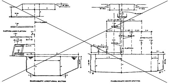
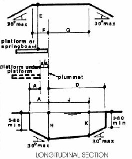
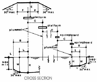
(Fire Prevention and Building Safety Commission; | Table 16-2 | ||||||||||
| FINA Dimensions for Diving Facilities | Dimensions Are in M (Feet) | SPRINGBOARD | PLATFORM | |||||||
| 1 Metres | 3 Metres | 1 Metre | 3 Metres | 5 Metres | 7.5 Metres | 10 Metres | ||||
| Length | 4.80m (15' - 8 31/32") | 4.80m (15' - 8 31/32") | 4.50m (14' - - 9 11/64") | 5.00m (16' - 4 27/64") | 6.00m (19' - 8 7/32") | 6.00m (19' - 8 7/32") | 6.00m (19' - 8 7/32") | |||
| Width | 0.50m (1' - 7 11/16") | 0.50m (1' - 7 11/16") | 0.60m (1' - 11 5/8") | 1.50m (4' - 11 1/16") | 1.50m (4' - 11 1/16") | 1.50m (4' - 11 1/16") | 2.00m (6' - 6 47/64") | |||
| Height | 1.00m (3' - 3 3/8") | 3.00m (9' - 10 7/64") | 0.60 - 1.00m (1' - 11 5/8" - - 3' - 3 - 3/8") | 2.60 - 3.00m (8' - 6 23/64" - 9' - 10 7/64") | 5.00m (16' - 2 27/64") | 7.50m (24' - 7 9/32") | 10.00m (32' - 9 45/64") | |||
| Horiz. | Horiz. | Horiz. | Horiz. | Horiz. | Horiz. | Horiz. | ||||
| Vert. | Vert. | Vert. | Vert. | Vert. | Vert. | Vert. | ||||
| A | From plummet BACK TO POOL WALL | Designation | A - 1 | A - 3 | A - 1p1 | A - 3p1 | A - 5 | A - 7.5 | A - 10 | |
| Minimum | 1.80m (5' - 10 55/64") | 1.80m (5' - 10 55/64") | 0.75m (2' - 5 17/32") | 1.25m (4' - 1 7/32") | 1.25m (4' - 1 7/32") | 1.50m (4' - 11 1/16") | 1.50m (4' - 11 1/16") | |||
| AA | From plummet BACK TO PLATFORM plummet directly below | Designation | AA 5/1 | AA 7.5/3/1 | AA 10/5/3/1 | |||||
| Minimum | 1.50m (4' - 11 1/16") | 1.50m (4' - 11 1/16") | 1.50m (4' - 11 1/16") | |||||||
| B | From plummet to POOL WALL AT SIDE | Designation | B - 1 | B - 3 | B - 1p1 | B - 3p1 | B - 5 | B - 7.5 | B - 10 | |
| Minimum | 2.50m (8' - 2 27/64") | 3.50m (11' - 5 51/64") | 2.30m (7' - 6 35/64") | 2.90m (9' - 6 11/64") | 4.25m (13' - 11 21/64") | 4.50m (14' - 9 11/64") | 5.25m (17' - 2 11/16") | |||
| C | From plummet to ADJACENT PLUMMET | Designation | C - 1/1 | C - 3/3/1 | C - 1/1p1 | C - 3/1 1/3p1 | C - 5/3/1 | C - 7.5/5 - 3 - 1 | C - 10/7.5/5 - 3 - 1 | |
| Minimum | 2.40m (7' - 10 31/64") | 2.60m (8' - 6 23/64") | 1.65m (5' - 4 61/64") | 2.10m (6' - 10 43/64") | 2.50m (8' - 2 27/64") | 2.50m (8' - 2 27/64") | 2.75m (9' - 0 17/64") | |||
| D | From plummet to POOL WALL AHEAD | Designation | D - 1 | D - 3 | D - 1p1 | D - 3p1 | D - 5 | D - 7.5 | D - 10 | |
| Minimum | 9.00m (29' - 6 21/64") | 10.25m (33' - 7 35/64") | 8.00m (26' - 2 61/64") | 9.50m (31' - 2 1/64") | 10.25m (33' - 7 35/64") | 11.00m (36' - 1 5/64") | 13.50m (44' - 3 1/2") | |||
| E | On plummet from BOARD TO CEILING | Designation | E - 1 | E - 3 | E - 1p1 | E - 3p1 | E - 5 | E - 7.5 | E - 10 | |
| Minimum | 5.00m (16' - 4 27/64") | 5.00m (16' - 4 27/64") | 3.50m (11' - 5 51/64") | 3.50m (11' - 5 51/64") | 3.50m (11' - 5 51/64") | 3.50m (11' - 5 51/64") | 5.00m (16' - 4 27/64") | |||
| F | CLEAR OVERHEAD behind and each side of plummet | Designation | F - 1 E - 1 | F - 3 E - 3 | F - 1p1 E - 1p1 | F - 3p1 E - 3p1 | F - 5 E - 5 | F - 7.5 E - 7.5 | F - 10 E - 10 | |
| Minimum | 2.50m (8' - 2 27/64") | 2.50m (8' - 2 27/64") | 2.75m (9' - 0 17/64") | 2.75m (9' - 0 17/64") | 2.75m (9' - 0 17/64") | 2.75m (9' - 0 17/64") | 2.75m (9' - 0 17/64") | |||
| 5.00m (16' - 4 27/64") | 5.00m (16' - 4 27/64") | 3.50m (11' - 5 51/64") | 3.50m (11' - 5 51/64") | 3.50 (11' - 5 51/64") | 3.50m (11' - - 5 51/64") | 5.00m (16' - 4 27/64") | ||||
| G | CLEAR OVERHEAD ahead of plummet | Designation | G - 1 | G - 3 | G - 1p1 | G - 3p1 | G - 5 | G - 7.5 | G - 10 | |
| E - 1 | E - 3 | E - 1p1 | E - 3p1 | E - 5 | E - 7.5 | E - 10 | ||||
| Minimum | 5.00m (16' - 4 27/64") | 5.00m (16' - 4 27/64") | 5.00m (16' - 2 27/64") | 5.00m (16' - 4 27/32") | 5.00m (16' - 4 27/64") | 5.00m (16' - 4 27/64") | 6.00m (19' - 8 7/32") | |||
| 5.00m (16' - 4 27/64") | 5.00m (16' - 4 27/64") | 3.50m (11' - 5 51/64") | 3.50m (11' - 5 51/64") | 3.50m (11' - 5 51/64") | 3.50m (11' - 5 51/64") | 5.00m (16' - 4 27/64") | ||||
| H | DEPTH OF WATER at plummet | Designation | H - 1 | H - 3 | H - 1p1 | H - 3p1 | H - 5 | H - 7.5 | H - 10 | |
| Minimum | 3.50m (11' - 5 51/64") | 3.80m (12' - 5 39/64") | 3.30m (10' - 9 59/64") | 3.60m (11' - 9 47/64") | 4.00m (13' - 1 31/64") | 4.50m (14' - 9 11/64") | 5.00m (16' - 4 27/32") | |||
| J K | DISTANCE AND DEPTH ahead of plummet | Designation | J - 1 K - 1 | J - 3 K - 3 | J - 1p1 K - 1p1 | J - 3p1 K - 3p1 | J - 5 K - 5 | J - 7.5 K - 7.5 | J - 10 K - 10 | |
| Minimum | 5.00m (16' - 4 27/64") | 6.00m (19' - 8 7/32") | 5.00m (16' - 4 21/64") | 6.00m (19' - 8 7/32") | 6.00m (19' - 8 7/32") | 8.00m (26' - 2 61/64") | 11.00m (36' - 1 5/64") | |||
| 3.40m (11' - 1 55/64") | 3.70m (12' - 1 43/64") | 3.20m (10' - 5 63/64") | 3.50m (11' - 5 51/64") | 3.90m (12' - 9 35/64") | 4.40m (14' - 5 15/64") | 4.75m (15' - 7 1/64") | ||||
| L M | DISTANCE AND DEPTH each side of plummet | Designation | L - 1 M - 1 | L - 3 M - 3 | L - 1p1 M - 1p1 | L - 3p1 M - 3p1 | L - 5 M - 5 | L - 7.5 M - 7.5 | L - 10 M - 10 | |
| Minimum | 1.50m (4' - 11 1/16") | 2.00m (6' - 6 47/64") | 1.40m (4' - 7 1/8") | 1.80m (5' - 10 55/64") | 4.25m (13' - 11 21/64") | 4.50m (14' - 9 11/64") | 5.25m (17' - 2 11/16") | |||
| 3.40m (11' - 1 55/64") | 3.70m (12' - 1 43/64") | 3.20m (10' - 5 63/64") | 3.50m (11' - 5 51/64") | 3.90m (12' - 9 35/64") | 4.40m (14' - 5 15/64") | 4.75m (15' - 7 1/64") | ||||
| N | MAXIMUM SLOPE TO REDUCE DIMENSIONS beyond full requirements | Pool Depth Ceiling Ht | 30 degrees 30 degrees | NOTE: Dimensions C (plummet to adjacent plummet) apply for Platforms with widths as detailed. For wider Platform increase C by half the additional width(s) | ||||||
SECTION 55. 675 IAC 20-2-17 IS AMENDED TO READ AS FOLLOWS:
675 IAC 20-2-17 Circulation systems
Authority: Sec. 17. (a) A circulation system consisting of:
(1) pumps;
(2) piping;
(3) overflows;
(4) skimmers;
(5) filters; and
(6) other necessary equipment;
shall be provided for complete and continuous circulation of water through all parts of the pool.
(b) The circulation system shall be of adequate size to produce not less than the following turnover times:
(1) Class A, Class B, and Class C diving pools: twelve (12) hours.
(2) Class A, Class B, and Class C pools without wading areas: six (6) hours.
(3) Class B and Class C pools with wading areas: two (2) hours.
(4) Class B and Class C wading pools: one (1) hour.
(5) Class B and Class C wave pools and zero (0) depth pools: two (2) hours.
(c) Circulation components that may require replacement or servicing shall be:
(1) accessible and available for inspection, repair, or replacement; and
(2) installed according to manufacturer's instructions.
(d) Materials and equipment used in the circulation system shall be of an approved type. Circulation systems and equipment within the scope of ANSI/NSF 50 (2009), shall:
(1) conform to ANSI/NSF 50 (2009) and bear the NSF endorsement seal, unless the manufacturer certifies the products are in compliance with ANSI/NSF 50 (2009); or
(2) be of a material suitable for water supply piping as specified in 675 IAC 16 . All exposed piping shall be color coded or provided with permanent labels or tags for easy identification.
(e) The water velocity in the pool piping shall not exceed ten (10) feet per second for discharge piping and six (6) feet per second for suction piping, unless summary calculations are provided to show that the greater flow is possible with the pump and piping provided. Pool piping shall be sized to permit the rated flows for filtering and cleaning without exceeding the maximum head at which the pump will provide such flows or exceeding the velocities stated. An exception is the water velocity in copper pipe shall not exceed eight (8) feet per second.
(f) The circulation piping and fittings shall be nontoxic and capable of withstanding operating pressures and conditions.
(g) The suction side of the circulation system shall be tied and split hydraulically equally between the two (2) or more main drains. outlets. Both branches shall have the same size pipe as the main drain. outlet.
(h) Pool piping shall:
(1) have a uniform slope in one (1) direction equipped with valves for adequate drainage; Pool piping shall and
(2) be supported at sufficient intervals to prevent entrapment of air, water, or dirt.
Provision shall be made for expansion or contraction of pipes.
(i) Equipment shall be designed and fabricated to drain the pool water from the equipment, together with exposed face piping, by removal of drain plugs and manipulating winter drain valves.
(j) A pressure or vacuum gauge or other means of indicating system condition shall be provided in the circulation system in an accessible location. Class A, Class B, and Class C pools shall be provided with an indicator measuring the rate of flow through the filter system with an appropriate range readable in gallons per minute and accurate within ten percent (10%) actual flow.
(k) When Time clocks are shall not be used to regulate the operation of circulation systems. they shall be set to regulate all circulation equipment and appurtenant devices.
(l) Operation and maintenance instructions, including a laminated pump curve or curves and conversion chart (psi to tdh), shall be provided for circulation system components.
(Fire Prevention and Building Safety Commission;
SECTION 56. 675 IAC 20-2-19 IS AMENDED TO READ AS FOLLOWS:
675 IAC 20-2-19 Pumps
Authority: Sec. 19. (a) A pump and motor shall be provided for circulation of the pool water. Performance of all pumps shall meet or exceed the conditions of flow required for filtering and cleaning (if applicable) the filters against the total dynamic head developed by the complete system.
(b) Water entering the pump or pumps shall pass through the removable strainer.
(c) Pumps shall be selected to perform the functions for which they were intended. Pumps and motors must be accessible for inspection and service.
(d) All motors shall have as a minimum an open, drip-proof enclosure and be constructed electrically and mechanically so they will perform satisfactorily under the conditions of load and environment normally encountered in swimming pool installations.
(e) Motors shall be capable of operating the pump under full load with a voltage variation of at least five percent (5%) from nameplate rating. If the maximum service factor of the motor is exceeded (at full voltage), the manufacturer shall indicate this on the pump curve.
(f) All motors shall have thermal or current overload protection, either built-in or in the line starter, to provide locked rotor and running protection.
(g) The motor frame shall contain adequate provisions for proper grounding. When a pump is installed below the waterline of a pool, valves shall be installed on permanently connected suction and discharge lines, located in a place outside the walls of the pool, where they will be readily accessible for maintenance and removal of the pump.
(h) Pressure and vacuum gauges shall be installed on all Class A and B swimming pools and the:
(1) the vacuum gauge shall be installed as close to the pump suction inlet as possible and still maintain an accurate reading; and
(2) the pressure gauge shall be installed on the face piping ahead of the filter or on the top of the filter in the area of greatest filter pressure.
(i) Where a mechanical pump seal is provided, components of the seal must be corrosion-resisting and capable of operating under conditions normally encountered in swimming pool operation.
(j) Pumps shall be of sufficient capacity to provide a minimum backwash rate of fifteen (15) gallons per square foot of filter area per minute in sand filter system. Pumps shall be of sufficient capacity to supply the recirculation rate of flow at a total dynamic head of at least:
(Fire Prevention and Building Safety Commission;
(1) fifty (50) feet for vacuum filters;
(2) seventy (70) feet for pressure sand or cartridge filters; and
(3) eighty (80) feet for pressure diatomaceous earth filters.
Pumps located at an elevation higher than the facility water line shall be self-priming.
SECTION 57. 675 IAC 20-2-20 IS AMENDED TO READ AS FOLLOWS:
675 IAC 20-2-20 Inlets
Authority: Sec. 20. (a) Pool inlets and outlets for circulated water shall be located to:
(1) produce uniform circulation of water; and to
(2) facilitate the maintenance of a uniform disinfectant residual throughout the entire pool.
Where skimmers are used, the inlets shall be located so as to help bring floating particles within range of the skimmers.
(b) The minimum number of inlets required shall be based on two (2) inlets per six hundred (600) square feet of pool surface area or fraction thereof.
(c) Inlets shall be sufficient in number such that the flow through any single inlet shall not exceed forty (40) gallons per minute.
(d) Wall Inlets shall be located not less than between twelve (12) inches below the waterline and no higher than the waterline.
(e) Pools with a width over thirty (30) feet shall have bottom inlets, if not equipped with a continuous gutter system with integral return inlets.
(f) Inlets shall be designed and installed so as not to provide a hazard to bathers.
(g) Inlets in facilities with skimmers shall be twelve (12) inches below the midpoint on the skimmer throat. Inlets in facilities with a prefabricated perimeter overflow system shall be eight (8) inches or more below the lip of the gutter.
(h) Inlets shall be placed completely around the pool, each serving a linear distance of not more than fifteen (15) feet on center. The pipe serving the inlets shall form a loop completely around the pool.
(i) At least one (1) inlet shall be located in each recessed stairwell or other space where water circulation might be impaired.
(Fire Prevention and Building Safety Commission;
SECTION 58. 675 IAC 20-2-20.1 IS ADDED TO READ AS FOLLOWS:
675 IAC 20-2-20.1 Outlets
Authority:
Sec. 20.1. (a) Pool outlets for circulated water shall be located to:
(1) produce uniform circulation of water; and
(2) facilitate the maintenance of a uniform disinfectant residual throughout the entire pool.
(b) Outlet drain covers and grates shall be installed in such a way that they cannot be removed without the use of tools.
(c) All pools shall be provided with a main outlet in the lowest point of the pool floor. All main drains smaller than a twelve (12) inch by twelve (12) inch grate shall be dual main outlets with a separation distance of three (3) feet between outlets in any dimension. All main outlets larger than a twelve (12) inch by twelve (12) inch grate shall be dual main outlets with a separation distance three (3) feet or more. The spacing of the main outlets for pool pump suction shall not be greater than thirty (30) feet on centers nor more than fifteen (15) feet from each side wall. See Table 20.1-1.
| Table 20.1-1 | |
| Flow rating for covers/grates | |
| Number of covers/grates per system | Minimum flow rating of each cover/grate % maximum system flow rate |
| 2 | 100% |
| 3 | 66.7% |
| 4 | 50% |
| 5 | 40% |
| 6 | 33.3% |
(d) The main outlet sumps shall be covered with suitable protective covers or grates. The total velocity through grate openings shall not exceed one and five-tenths (1.5) feet/second for flow through for suction grates. The grate opening shall not exceed one-quarter (1/4) inch.
(e) Main outlet piping shall be sized for removal of the water through it at a rate of at least one hundred percent (100%) of the design circulation flow rate at velocities specified in 675 IAC 20-2-18 (e). It shall function as part of the circulation system. The piping system shall be valved to permit adjustment of flow through it.
(f) Main outlets shall conform to the requirements for ASME A112.19.8, 2007 Edition.
(Fire Prevention and Building Safety Commission;
SECTION 59. 675 IAC 20-2-21 IS AMENDED TO READ AS FOLLOWS:
675 IAC 20-2-21 Surface skimmer systems
Authority: Sec. 21. (a) A surface skimming system shall be:
(1) provided on all public swimming pools; and shall be
(2) designed and constructed to skim the pool surface when the water level is maintained within the operational parameters of the system's rim or weir device.
(b) When perimeter-type surface skimming systems are provided, they shall meet the following:
(1) Overflow gutters shall extend completely around the pool perimeter with the exception of the following:
(A) Where the gutters would interfere with a means of entry and exit.
(B) "Wave pools" and "zero (0) depth pools".
(2) Overflow gutters shall be capable of continuously removing not less than one hundred percent (100%) of the recirculated water or one (1) gallon per minute per lineal foot of pool perimeter, whichever is greater.
(3) The opening into the gutter beneath the coping shall not be not less than four (4) inches, and the interior of the gutter shall not be not less than three (3) inches in width or depth.
(4) The overflow edge (lip) shall be rounded and no thicker than two and one-half (2 1/2) inches for the top two (2) inches.
(5) Overflow outlets shall be:
(A) not less than two (2) inches in diameter; and shall be
(B) sufficiently spaced so as to maintain the gutters in a self-cleaning and effective state without discharging back into the pool.
(6) All facilities that have perimeter overflow systems shall be provided with a net surge capacity of at least one (1.0) gallon per square foot of water surface area. Surge capacity shall be provided either in a vacuum filter tank, in the perimeter overflow system, in a surge tank, or a combination thereof. Valving shall be provided where necessary, to automatically retain water during periods of facility use and to discharge water during the periods of nonuse so that the proper operating water level in the facility is maintained at all times.
(7) Perimeter-type surface skimmers shall be designed for removal of water from the pool's upper surface at a rate equal to one hundred percent (100%) of the design turnover flow rate. If the surge volume is to be stored in the perimeter overflow system, the system shall have the capacity to carry one hundred percent (100%) of the design flow while maintaining the surge storage capacity.
(8) Surge weirs shall pass at least fifty percent (50%) of the design circulation flow rate with the water level at the mid-level of the weir. A minimum of one (1) weir shall be provided for each five hundred (500) square feet of pool water surface area or fraction thereof. The combined flow rate through all the surge weirs shall not exceed the design circulation flow rate. Surge weirs shall be uniformly spaced around the pool perimeter. The mid-level of the weir opening shall be at least one (1) inch but not more than two (2) inches below the overflow lip of the perimeter overflow system. A flow-regulating device that will maintain a relatively constant flow rate as the water level is varied shall be included. Surge weirs shall not be utilized at a zero-depth pool.
(c) Skimmers shall not be installed in pools over thirty (30) feet in width, and, when installed in pools under thirty (30) feet wide, they shall meet the following:
(Fire Prevention and Building Safety Commission; (1) Only be installed where an approved handhold is provided around the perimeter of the pool.
(2) One (1) skimmer shall be provided for every five hundred (500) square feet of pool surface area, or fraction thereof.
(3) Skimming devices shall:
(A) be installed in the pool wall; and shall
(B) develop sufficient velocity on the water surface to induce floating oils and wastes into the skimmer or skimmers from the entire pool area.
(4) The skimmer weir or weirs shall:
(A) be automatically adjustable; and shall
(B) operate freely with continuous action to variations in water level over a range of at least four (4) inches; and shall
(C) operate at all flow variations.
(5) No equalizer shall be used nor shall the main outlet be connected to the recirculation circulation system through a skimmer.
(6) The skimmer shall be of sturdy, corrosion-resistant materials with an easily removable and cleanable basket or screen through which all overflow water must pass.
SECTION 60. 675 IAC 20-2-22 IS AMENDED TO READ AS FOLLOWS:
675 IAC 20-2-22 Electrical, mechanical, and illumination requirements
Authority: Sec. 22. (a) The requirements of 675 IAC 17 , the Indiana Electrical Code, shall be followed for the wiring, grounding, bonding, and installation of electrical equipment and metallic appurtenances to the pool.
(b) Artificial lighting shall be provided for all pools to be used indoors or pools used during periods of darkness. Such lighting shall be sufficient to make a six (6) inch black disc, placed on a white background clearly visible from the side of the pool when that disc is placed on the floor of the pool. provide clear visibility in the pool area for all pools that are to be used at night, or when natural lighting is insufficient, to provide the following:
(1) Lighting fixtures shall be of such number and design as to illuminate all parts of the pool, the water, the depth markers, signs, entrances, restrooms, safety equipment, and the required deck area and walkways.
(2) Overhead lights. There shall be no light fixtures directly above the water surface.
(3) Fixtures shall be installed so as not to create hazards such as burning, electrical shock, mechanical injury, or temporary blinding by glare to the bathers, and so that lifeguards, when provided, can clearly see every part of the pool area without being blinded by glare. The illumination shall be sufficient so that the floor of the pool can be seen at all times the pool is in use.
(4) Underwater lighting shall provide at least five-tenths (0.5) watt or eight and thirty-five hundredths (8.35) lumens per square foot of water surface.
(5) Area lighting shall provide at least six-tenths (0.6) watt or ten (10) lumens per square foot of required deck area when underwater lighting is used. Where underwater lighting is not used, and night swimming is permitted, area and pool lighting combined shall provide not less than two and zero-tenths (2.0) watts or thirty-three and five-tenths (33.5) lumens per square foot of pool and required deck area.
(6) Portable electric vacuum cleaning equipment is used, electrical receptacles with ground-fault circuit interrupter protection shall be provided. Separation between receptacles shall be a maximum of one hundred (100) feet. All receptacles installed in the swimming pool area shall have waterproof covers and ground-fault circuit interrupter protection.
(7) Light dimmers may not be installed on underwater lighting or lights for the pool deck.
(8) Lighting controls shall not be accessible to the public.
(c) Mechanical equipment shall be designed and installed in accordance with the requirements of 675 IAC 18 , the Indiana Mechanical Code. Corrosion-resistant fan and ductwork shall be installed in the enclosed disinfectant chemical feed room or rooms.
(d) Heaters shall be installed and tested to comply with the requirements under the Indiana Fuel Gas Code for gas applications or the Indiana Electrical Code for electrical applications.
(Fire Prevention and Building Safety Commission;
SECTION 61. 675 IAC 20-2-26 IS AMENDED TO READ AS FOLLOWS:
675 IAC 20-2-26 Safety requirements
Authority: Sec. 26. (a) Pools shall be provided with a suitable handhold around their perimeter in areas where depths exceed three (3) feet six (6) inches. Handholds shall be provided no farther apart than four (4) feet and may consist of any one (1) or a combination of the following:
(1) Coping, ledge, or deck along the immediate top edge of a pool that provides a slip-resisting surface of at least a four (4) inch minimum horizontal width located not over twelve (12) inches above the waterline.
(2) Ladders, stairs, or seat ledges.
(3) A railing fastened to the wall placed not over twelve (12) inches above the waterline.
(b) A transition line shall be provided between within one (1) foot and two (2) feet on the shallow side of the break in grade between the shallow and deep portions of the swimming pools, with its position marked with visible floats at not greater than seven (7) feet intervals. This transition line shall be securely fastened to wall anchors of corrosion-resisting materials and of the type which shall be recessed.
(c) Depth of water in feet and inches shall be plainly and conspicuously marked at or above the water surface on the vertical pool wall above the waterline as much as possible and on the top of coping or edge of the deck or walk next to the pool as follows:
(1) Depth markers on the deck shall be within eighteen (18) inches of the water edge, and positioned to be read while standing on the deck facing the water, and of slip-resistant material.
(2) Depth markers shall be installed at the maximum and minimum water depths and at all points of slope change and at intermediate increments of water depth not to exceed two (2) feet, at intervals of twenty-five (25) feet or less.
(3) Depth numbers shall not be:
(A) not less than four (4) inches minimum in height;
(B) permanently colored; and
(C) in contrast to the background on which they are applied.
(4) "No Diving" symbols shall be placed on the deck at twenty-five (25) foot minimum intervals where the pool depth is five (5) feet or less.
(d) Lifeguard chairs are required for all pools over two thousand (2,000) square feet at a rate of one (1) chair per every two thousand (2,000) square feet of water surface.
(e) All Class A, Class B, and Class C pools shall be furnished in an accessible location with not less than the following:
(1) One (1) United States Coast Guard approved ring buoy or rescue tube with a fifteen (15) inch minimum diameter attached to a one-fourth (1/4) inch diameter throwing line equal to one and one-half (1 1/2) times the maximum width of the pool but not to exceed forty-five (45) feet in length. An exception is a rescue tube is a permitted alternative to the ring buoy at locations where lifeguards are on duty during operational hours.
(2) One (1) shepherd's hook with a pole not less than twelve (12) feet long.
(3) One (1) twenty-four (24) unit first aid kit.
(4) Access to A telephone located within three hundred (300) feet of the pool, with posted names and emergency numbers for the nearest police, fire, and emergency responders or 9-1-1, or both.
(f) All Class A, Class B, and Class C pools shall be enclosed by a fence, wall, building, or other enclosures that are not less than six (6) feet high, to aid in the control of the movement of bathers and to discourage the entrance of unwanted persons. Enclosure shall be equipped with a self-closing and positive self-latching closure mechanism at a height of at least forty-five (45) inches (one hundred fourteen (114) cm) above the ground and provided with hardware for locking. Where the release mechanism is located less than fifty-four (54) inches (one hundred thirty-seven (137) cm) from the bottom of the gate, the release mechanism and openings shall comply with the following:
(1) The release mechanism shall be located on the pool side of the gate at least three (3) inches (eight (8) cm) below the top of the gate.
(2) The gate and barrier shall have no openings greater than one-half (1/2) inch (one and three-tenths (1.3) cm) within eighteen (18) inches (forty-six (46) cm) of the release mechanism.
(3) The barrier shall have no opening that allows the passage of a four (4) inch (ten (10) cm) diameter sphere.
(g) One barrier shall be permitted to surround multiple pools. An exception is a barrier shall be provided to separate pools of four (4) feet of depth or less from those with more than four (4) foot of depth.
(Fire Prevention and Building Safety Commission;
SECTION 62. 675 IAC 20-2-27 IS AMENDED TO READ AS FOLLOWS:
675 IAC 20-2-27 Bathhouse construction standards
Authority: Sec. 27. (a) Dressing, shower, and sanitary facilities, and baby-changing stations for each sex shall be provided within three hundred (300) feet of all Class A, B, and C pools.
(b) In all Class A and B pools, such facilities shall be provided in a separate bathhouse located in such a manner that bathers must pass through the bathhouse to gain entry to the pool. Said The bathhouse shall not be required to be a separate building.
(c) Design and construction of bathhouses shall be in accordance with the rules of the fire prevention and building safety commission in this title. Minimum plumbing facilities for bathers patrons shall be in accordance with the following Table 27-1 as follows:
| Table 27-1 | |||||||||
| MINIMUM NUMBER OF SANITARY FIXTURES REQUIRED AT PUBLIC POOLS | |||||||||
| Facility (example of location and type)a | Cumulative Area of Surface Water (in square feet) | Number of | |||||||
| Public Toilets | Public Urinals | Public Lavatories | Public Showers | Public Drinking Fountains | |||||
| F | M | M | F | M | F | M | |||
| 1. Swimming pools, wading pools, and whirlpools in conjunction with sleeping or dwelling units having plumbing, except for items 2 to 5. No open swim lessons permitted (that is, apartment, hotels, motels, condos, and mobile home parks) | < 2,000 | One unisex | 0 | One unisex | 0 | 0 | 1a | ||
| 2,000 - 7,500 | 1 | 1 | 0 | 1 | 1 | 1 | 1 | 1 | |
| > 7,500 | See note b below for requirements. | ||||||||
| 2. Swimming pools, wading pools, and whirlpools without living units, except for items 3 to 5; and swimming pools, wading pools, and whirlpools with sleeping or dwelling units where open swim or lessons are permitted (that is, municipal pools and campgrounds) | < 2,000 | 1 | 1 | 0 | 1 | 1 | 1 | 1 | 1 |
| 2,000 - 3,999 | 3 | 1 | 2 | 1 | 1 | 2 | 2 | 1 | |
| 4,000 - 5,999 | 4 | 2 | 2 | 2 | 2 | 4 | 4 | 1 | |
| 6,000 - 7,499 | 4 | 2 | 2 | 2 | 2 | 5 | 5 | 1 | |
| 7,500 - 8,999 | 8 | 2 | 2 | 3 | 2 | 5 | 5 | 2 | |
| 9,000 - 9,999 | 10 | 2 | 3 | 4 | 3 | 6 | 6 | 2 | |
| 10,000 - 12,999 | 12 | 3 | 3 | 4 | 3 | 6 | 6 | 2 | |
| 13,000 - 15,000 | 14 | 3 | 4 | 5 | 4 | 7 | 7 | 3 | |
| >15,000 | See note below for requirements. | ||||||||
| 5. Splash pad (independent of any other pool or attraction) | One unisex | 0 | One unisex | One rinse off shower | 1 | ||||
| Patron Load | |||||||||
| 6. Therapy/Exercise pools. | Up to 10 | One Unisex | |||||||
| 11 - 20 | 2 | 1 | 1 | 1 | 1 | 2 | 2 | 1 | |
| 21 - 30 | 2 | 1 | 1 | 2 | 2 | 3 | 3 | 1 | |
| > 30 | Per department approval | ||||||||
| F = female; M = male; < = less than; > = greater than | |||||||||
| a For pools with spectator areas, see |
|||||||||
(d) Hose bibbs with approved nonremovable type backflow prevention devices shall be provided within the bathhouse to enable the entire area to be flushed with a fifty (50) foot hose.
SECTION 63. 675 IAC 20-3-0.5 IS ADDED TO READ AS FOLLOWS:
675 IAC 20-3-0.5 Content of plans; filing requirements
Authority:
Sec. 0.5. (a) Plans and specifications of all public spas shall be submitted under 675 IAC 12-6 for design release prior to the construction, rehabilitation, or alteration of any public spa.
(b) All projects required to comply with this article shall be prepared by a design professional and submitted in accordance with 675 IAC 12-6 .
(c) The plans and specifications shall contain sufficient information to show that the spa, spa systems, bathhouse, equipment, or improvements thereto will meet the requirements of this code and shall indicate not less than the following:
(1) A physical description of the spa including the following:
(A) Spa perimeter.
(B) Spa area.
(C) Spa depths.
(D) The location of inlets and outlets.
(E) Waterline.
(F) Stairs.
(G) Materials of construction.
(2) Spa volume, turnover, rate of filtration, flow rates, and total dynamic head.
(3) The source, quality, and characteristics of the make-up water supply.
(4) A detailed description of filtration, circulation, and chemical feeder equipment.
(5) Scale and north point.
(6) Bather load.
(d) This section shall not be considered as a substitute for the requirements of 675 IAC 12-6 on the submission of plans and specifications for spas, their appurtenant equipment, decks, bathhouses, and appliances necessary to maintain the spa in a safe and sanitary condition.
(Fire Prevention and Building Safety Commission;
SECTION 64. 675 IAC 20-3-5 IS AMENDED TO READ AS FOLLOWS:
675 IAC 20-3-5 Electrical, mechanical, and illumination requirements
Authority: Sec. 5. (a) Mechanical equipment shall be installed in accordance with 675 IAC 18 , the Indiana Mechanical Code.
(b) Electrical equipment, system wiring, and grounding of all spa equipment and appurtenances shall be in accordance with 675 IAC 17 , the Indiana Electrical Code.
(c) An emergency shutdown device shall be installed that will immediately cut power to the pump serving the main drains. outlets. This emergency shutdown device shall be:
(1) readily accessible in the event of an emergency; This device shall be
(2) distinctly labeled as EMERGENCY SPA SHUTDOWN DEVICE; This device shall be and
(3) installed in the same room as the spa and within site of the spa.
(d) The water supply serving the spa shall meet 327 IAC, the rules of the water pollution control board, before any bather uses the spa.
(Fire Prevention and Building Safety Commission;
SECTION 65. 675 IAC 20-3-6 IS AMENDED TO READ AS FOLLOWS:
675 IAC 20-3-6 Inlets
Authority: Sec. 6. (a) Spa inlets and outlets shall be arranged to produce a uniform circulation of water throughout the spa.
(b) Water velocity in the spa piping shall not exceed ten (10) feet per second with the following exceptions:
(1) Suction velocity shall not exceed six (6) feet per second.
(2) Water velocity in existing asbestos cement pipe shall not exceed six (6) feet per second.
(3) Water velocity in copper pipe shall not exceed eight (8) feet per second.
SECTION 66. 675 IAC 20-3-6.1 IS ADDED TO READ AS FOLLOWS:
675 IAC 20-3-6.1 Outlets
Authority:
Sec. 6.1. (a) Spa inlets and outlets shall be arranged to:
(1) produce a uniform circulation of water; and
(2) facilitate the maintenance of a uniform disinfectant residual throughout the spa.
(b) Water velocity in the spa piping shall not exceed ten (10) feet per second with the following exceptions:
(1) Suction velocity shall not exceed six (6) feet per second.
(2) Water velocity in existing asbestos cement pipe shall not exceed six (6) feet per second.
(3) Water velocity in copper pipe shall not exceed eight (8) feet per second.
(c) Total velocity through grate openings shall not exceed one and one-half (1.5) feet per second.
(d) All outlets below the waterline shall be covered with either a protective grate with individual openings of three-eighths (3/8) of an inch or less.
(e) All spas shall have a surface skimming (overflow) system and dual drain outlets at the lowest point on the spa floor. The dual outlets shall be spaced at least three (3) feet apart. When skimmers are the sole overflow system, not less than one (1) skimmer shall be provided for each one hundred (100) square feet, or portion thereof, of water surface.
(f) Main outlets shall conform to the requirements for ASME A112.19.8, 2007 edition.
(Fire Prevention and Building Safety Commission;
SECTION 67. 675 IAC 20-3-7 IS AMENDED TO READ AS FOLLOWS:
675 IAC 20-3-7 Circulation systems
Authority: Sec. 7. (a) Every spa shall be provided with an approved type circulation system capable of turning over the entire spa water capacity in not less than thirty (30) minutes.
(b) All circulation shall:
(1) go through the spa filtration system; and
(2) be chemically treated prior to injection into the spa.
(c) A removable strainer or screen shall be installed upstream from all pumps.
(d) Filters shall meet the following requirements:
(1) They shall be capable of maintaining the standards of turbidity set by the Indiana state department of health.
(2) They shall be provided with a means to safely release air which that builds up in the filter tank.
(3) Piping furnished with the filter system shall be capable of withstanding three (3) times the designed working pressure.
(4) The suction side of the circulation system shall be tied and split hydraulically equally between the two (2) or more main drains. outlets. Both branches shall have the same size pipe as the main drain. outlet.
(5) All filters and their components shall be accessible.
(e) Air induction systems, when provided, shall:
(1) prevent water backup; and shall
(2) not introduce contaminants into the spa water.
(f) Chemical feeder systems shall be provided, capable of maintaining a chemical residual and pH level in accordance with 410 IAC, the rules of the Indiana state department of health.
(g) Operation and maintenance instructions, including a laminated pump curve or curves and conversion chart (psi to tdh) shall be provided for circulation system components.
(Fire Prevention and Building Safety Commission;
SECTION 68. 675 IAC 20-3-10 IS ADDED TO READ AS FOLLOWS:
675 IAC 20-3-10 Disinfectant equipment and chemical feeders
Authority:
Sec. 10. Disinfectant equipment and chemical feeders shall be as follows:
(Fire Prevention and Building Safety Commission;
(1) Capable of automatically providing a continuous residual chemical effect in accordance with 410 IAC, the rules of the Indiana state department of health.
(2) Of an approved type.
(3) Installed downstream from the pump.
(4) Wired so they will not operate unless the filter pump is operating.
An exception is erosion-type chlorinators may feed their solution to the suction side of the pump.
SECTION 69. 675 IAC 20-3-11 IS ADDED TO READ AS FOLLOWS:
675 IAC 20-3-11 Water supply
Authority:
Sec. 11. (a) The water supply serving the spa shall meet 327 IAC, the rules of the water pollution control board, before any bather uses the spa.
(b) No direct mechanical connection shall be made between the potable water supply and the pool, disinfectant equipment, chemical feeders, or system piping for the pool unless it is protected against backflow and siphonage in a manner acceptable under 675 IAC 16 , the Indiana Plumbing Code, or through an approved airgap meeting that same code.
(Fire Prevention and Building Safety Commission;
SECTION 70. 675 IAC 20-5 IS ADDED TO READ AS FOLLOWS:
Rule 5. Water Attractions
675 IAC 20-5-1 Water attractions, water attraction complexes; general
Authority:
Sec. 1. (a) Any new construction or alteration of a water attraction or water attraction complex shall be designed and installed as specified under this rule.
(b) Wading pools are not water attractions and shall conform to 675 IAC 20-2 .
(Fire Prevention and Building Safety Commission;
675 IAC 20-5-2 Content of plans; filing requirements
Authority:
Sec. 2. (a) Plans and specifications for all water attractions shall be submitted under 675 IAC 12 , the general administrative rules, for design release prior to the construction, rehabilitation, or alteration of any public water attraction or semipublic water attraction.
(1) In the event of conflict, see 675 IAC 12-4-8 .
(2) Plans and specifications for a public water attraction or a semipublic water attraction shall be prepared under the supervision of and be certified by a design professional, as defined in 675 IAC 12-6-2 .
(b) The plans and specifications shall contain sufficient information to show that the water attraction, its systems, bathhouse, equipment, or improvements thereto will meet the requirements of this code and shall indicate not less than the following:
(1) A physical description of the water attraction including the following:
(A) Perimeter.
(B) Area.
(C) Depths.
(D) Location of inlets and outlets.
(E) Waterline.
(F) Stairs.
(G) Ladders.
(H) Diving equipment.
(I) Materials of construction.
(2) Volume, turnover, rate of filtration, flow rates, and total dynamic head.
(3) Source, quality, and characteristics of the make-up water supply.
(4) A detailed description of filtration, circulation, and chemical feeder equipment.
(5) Scale and north point.
(c) This section shall not be considered as a substitute for the requirements of 675 IAC 12 , the general administrative rules, on the submission of plans and specifications for water attractions, their appurtenant equipment, decks, bathhouses, and appliances necessary to maintain the facility in a safe and sanitary condition.
(Fire Prevention and Building Safety Commission;
675 IAC 20-5-3 Materials of construction
Authority:
Sec. 3. Water attractions and all appurtenances thereto shall be constructed of materials that:
(Fire Prevention and Building Safety Commission;
(1) are nontoxic to humans and the environment;
(2) are impervious and enduring;
(3) can withstand the design stresses;
(4) will provide a watertight structure with an easily cleaned surface without cracks or joints, excluding structural joints; or
(5) an easily cleaned surface finish is applied or attached.
675 IAC 20-5-4 Structural design
Authority:
Sec. 4. (a) All water attractions shall be designed and constructed to withstand all anticipated loading for both empty and full conditions, and a hydrostatic relief valve shall be provided for all in-ground water attractions. The design professional as described in 675 IAC 12-6 shall be responsible for ensuring that the design and construction comply with the requirements for the structural stability as described above.
(b) Sand or earth shall not be permitted as an interior finish in a public water attraction.
(c) In all water attractions not completely enclosed in a heated building, the shell and appurtenances, piping, filter system, pump, motor, and other components shall be so designed and constructed to facilitate protection from damage due to freezing.
(d) The surfaces within a water attraction intended to provide footing for bathers shall be designed to provide a slip-resisting surface. The roughness or irregularity of the surfaces shall not provide an abrasion hazard to the feet during normal use.
(e) The color, pattern, or finish of the basin interior shall not obscure the existence or presence of objects or surfaces within the structure. The floor of all water attractions shall be white, light colored, or light colored patterns in order to facilitate the identification of any objects. "Light colored" means having a light reflectance value (LRV) of fifty percent (50%) or more.
(f) The splash zone shall be sloped to drain to the surge tank or pool within the same basin.
(g) The maximum floor slope to drain of the splash zone shall be 1:12.
(h) All exterior walking surfaces shall be sloped to drain away from the splash zone.
(Fire Prevention and Building Safety Commission;
675 IAC 20-5-5 Dimensional design
Authority:
Sec. 5. (a) No limits are specified for the shape of water attractions except that consideration shall be given to shape from the standpoint of safety and circulation of the water.
(b) There shall be no protrusions, extensions, means of entanglement, or other obstructions in the bathing area that can cause the entrapment or injury of the bather.
(1) At no time shall interior basin divider walls be submerged during operation.
(2) Interior basin divider walls shall not exceed eighteen (18) inches in width.
(c) There shall be construction tolerances allowed on all dimensional designs. See Table 5-1 as follows:
| Table 5-1 | |
| PERMITTED CONSTRUCTION TOLERANCES FOR WATER ATTRACTIONS | |
| Design Requirement | Permitted Construction Tolerances (in inches, unless otherwise noted) |
| Length, overall | + 3 |
| Width, overall | + 3 |
| Depth, deep area a, b | + 3 |
| Depth, shallow area b, c | + 2 |
| Floor nozzle flushness | + 1/8 |
| Stair tread and riser uniformity d | + 3/8 |
| Waterline, water attractions with adjustable weir skimmers | + 1/4 |
| Waterline, water attractions with nonadjustable skimming system (that is, gutters and zero-depth overflow trenches) | + 1/8 |
| Walls | + 3 degrees |
| Other dimensions not specified above | + 2 |
| a As measured at a location measured from the basin wall equal to 60% of the nominal basin depth and at the location of the depth marking. | |
| b For dimension requirements for diving wells, see Rule 2. | |
| c As measured 3 feet from the basin wall at the location of the depth marking. | |
| d Except as allowed by |
|
(d) Design requirements as listed in Table 5-2 shall be applied to all water attractions under the scope of this rule as follows:
(Fire Prevention and Building Safety Commission; | Table 5-2 | |||||
| DESIGN REQUIREMENTS BY WATER ATTRACTION TYPE | |||||
| Water Attraction Type | |||||
| Parameter | Activity | Leisure River | Plunge | Vortex | Wave |
| Access entry provisions | Limited by design | Limited by design | Slide only | Limited by design | Beach end |
| Maximum floor slope | 1:12 | 1:12 | 1:7 | 1:12 | 1:12 |
| Maximum allowed depth | NR | 42 in. | NR | 42 in. | NR |
| NR = Not Required. | |||||
675 IAC 20-5-6 Floor
Authority:
Sec. 6. (a) All slopes shall be uniform and shall slope to the drain or the water evacuation area.
(1) Where water depths are less than five (5) feet, floor slopes shall not exceed 1:12.
(2) Where the water depth is five (5) feet or more, floor slopes shall not exceed 1:3.
(b) When a transitional radius is provided between the basin wall and floor, it shall be as follows:
(Fire Prevention and Building Safety Commission;
(1) The radius shall have its center not less than two (2) feet nine (9) inches below the waterline in deep areas or two (2) feet six (6) inches in the shallow area.
(2) The radius shall be tangent to the wall.
(3) The radius shall be at least equal to, or greater than, the depth of the basin minus the vertical wall depth measured at the waterline minus three (3) inches to allow draining to the main outlet.
675 IAC 20-5-7 Walls
Authority:
Sec. 7. Basin walls shall be vertical or within eleven (11) degrees of vertical for a minimum distance of two (2) feet nine (9) inches from the waterline in deep areas or two (2) feet three (3) inches in shallow areas and curved to join the floor.
(Fire Prevention and Building Safety Commission;
675 IAC 20-5-8 Depths
Authority:
Sec. 8. (a) The transition point between the wading area and deeper areas of a water attraction shall be visually set apart with depth numbers, a four (4) inch width row of floor tile, painted line, or similar means of a color contrasting with the bottom. In all basins with diving equipment, the shallow area shall be visually set apart from the deep area with a transition line, depth numbers, and a four (4) inch color contrasting with the bottom.
(b) The water depth of all water attractions shall be as established by the manufacturer.
(c) Activity pools having a patron accessible depth greater than five (5) feet shall have a transition line as specified.
(Fire Prevention and Building Safety Commission;
675 IAC 20-5-9 Diving equipment
Authority:
Sec. 9. When diving equipment is installed in a water attraction, it shall conform to 675 IAC 20-2 .
(Fire Prevention and Building Safety Commission;
675 IAC 20-5-10 Offset ledges
Authority:
Sec. 10. (a) Offset ledges, when provided, shall:
(1) fall within eleven (11) degrees from vertical starting at the junction of the basin wall and waterline; and
(2) have a slip-resisting surface.
(b) The offset ledge edge shall be visually set apart with a minimum two (2) inch width row of floor tile, painted line, or similar means of a color contrasting with the bottom.
(Fire Prevention and Building Safety Commission;
675 IAC 20-5-11 Separation distance
Authority:
Sec. 11. Separate wading pools and interactive play attractions shall be physically set apart by at least twenty (20) feet from water attraction basins deeper than twenty-four (24) inches or by a barrier, not less than four (4) feet high, that creates a minimum travel distance of twenty (20) feet.
(Fire Prevention and Building Safety Commission;
675 IAC 20-5-12 Deck requirements
Authority:
Sec. 12. (a) Deck work shall be designed and installed so as to include the quality of subbase, concrete mix design, reinforcing, joints, and finishes. Work performed in accordance with the American Concrete Institute (ACI) Standard 302.1R-04, "Guide for Concrete Floor and Slab Construction" complies with this requirement.
(b) Decks, ramps, and similar surfaces, including step treads and coping, shall be slip-resistant and easily cleanable. The roughness or irregularity of the surfaces shall not cause injury or provide an abrasion during normal use. Depth markers, pool brand insignias, or similar special features located in or on the deck shall conform to this section.
(c) Deck surfaces shall be provided at all perimeter areas of water attractions specified as entry or exit points.
(d) Deck surfaces shall be of nontoxic, natural or man-made, impervious materials.
(e) Steps for the deck outside the perimeter shall be in accordance with 675 IAC 13 , the Indiana Building Code.
(f) The unobstructed deck width provided around deck equipment, including:
(1) handrails;
(2) structural support columns;
(3) lifeguard chairs; and
(4) play equipment;
shall be a minimum of four (4) feet.
(g) Water attractions with basins of five (5) feet of depth or more shall have an unobstructed, continuous deck with a minimum of three (3) feet in width.
(h) The maximum slope of decks shall be one-half (1/2) inch per foot with a minimum slope of one-eighth (1/8) inch per foot. An exception is access ramps where the maximum slope shall be one (1) inch per foot.
(i) The maximum width of voids between adjoining concrete slabs or between concrete slabs and expansion joint material, or both, shall be three-sixteenths (3/16) inch of horizontal clearance with a maximum difference in vertical elevation of one-fourth (1/4) inch. Any gap wider than three-sixteenths (3/16) inch shall be filled with suitable caulking material in accordance with the material supplier's specifications.
(j) Joints, where the coping meets the concrete decks, shall be watertight.
(1) Where deck work joins the coping, the joining areas shall be designed and installed so as to adequately protect the basin and its mortar bed from damage.
(2) The area where pool decks join existing concrete work shall be protected by an expansion joint to protect the pool from the pressures of relative movements.
(k) Control joints in concrete decks shall be provided to minimize the potential for cracks due to a change in elevations, separation of surfaces, or movement of the slab.
(l) Decks shall be edged, provided with a radius, or otherwise relieved so as to prevent exposed sharp corners.
(m) Decks shall be sloped to effectively drain either to perimeter areas or to deck drains. Drainage shall remove splash water, deck cleaning water, and rainwater. Site drainage shall be provided away from all decks so as to direct all perimeter deck drainage as well as general site drainage away from decks. Deck draining systems, when used, shall not drain more than four hundred (400) square feet to a single drain or twenty-five (25) feet of deck perpendicular to a continuous drain.
(n) Open pit (leeching design) for backwash sump purposes shall be located so that it falls completely below adjacent deck work and fully outside a line projected forty-five (45) degrees downward and away from the deck work.
(o) Circulation system piping, other than that integrally included in the manufacture of the water attraction, shall be subject to an induced static hydraulic pressure test (sealed system) at twenty-five (25) pounds per square inch for thirty (30) minutes. This test shall be performed before the deck is poured, and the pressure shall be maintained through the deck pour.
(p) Valves installed in or under a deck shall be covered and readily accessible for operation, service, and maintenance.
(q) All hose bibbs shall be fitted with vacuum breakers. At least one (1) hose bibb shall be provided in the equipment room. An additional hose bibb shall be provided in each toilet facility and at intervals along the deck so as to permit adequate cleaning using a maximum of one hundred (100) feet of hose. A hose bibb in the equipment room or dressing, shower, or toilet facility may be used for deck cleaning if located where a door opens directly to the deck and so that not more than one hundred (100) feet of hose, when laid across the deck surface, is needed to reach all areas of the deck.
(r) Water powered devices, such as, but not limited to, water powered lifts, shall have a dedicated hose bibb. Hoses for water powered devices shall be so located so as not to create a tripping hazard.
(s) Access to one (1) or more drinking fountains, installed in accordance with 675 IAC 16 , shall be provided within three hundred (300) feet of all water attractions.
(Fire Prevention and Building Safety Commission;
675 IAC 20-5-13 Means of entry and exit
Authority:
Sec. 13. (a) All public water attractions shall have not less than two (2) means of entry and exit located so as to serve opposite sides of the basin. Basins or water areas over thirty (30) feet in width shall have not less than one (1) means of entry and exit on each side. Not less than one (1) means of entry and exit shall be provided for each seventy-five (75) linear feet, or fraction thereof, of basin perimeter. An exception is leisure rivers with one (1) means of entry and exit every one hundred fifty (150) feet of basin perimeter.
(b) Where water depths are twenty-four (24) inches or less at the basin wall, the basins shall be considered as providing their own natural means of entry and exit.
(c) The design and construction of protruding and recessed stairs and ramps within a basin shall conform to the following:
(1) Stair treads shall have a minimum unobstructed horizontal tread depth of ten (10) inches and a minimum unobstructed surface area of two hundred forty (240) square inches. The nose of the stair tread shall:
(A) have a slip-resistant surface finish; and
(B) be visually set apart with a minimum two (2) inch width row of floor tile, painted line, or similar means of a color contrasting with the bottom.
(2) Risers at the center line of the treads shall have a maximum uniform height of twelve (12) inches with the bottom riser height allowed to vary plus or minus two (2) inches from the uniform riser height.
(3) Each set of stairs or each ramp shall be provided with at least one (1) handrail to fully serve all treads and risers. Handrails shall conform to the following:
(A) Handrails, if removable, shall be installed in such a way that they cannot be removed without the use of tools.
(B) The leading edge of handrails facilitating steps and exit must be located within eighteen (18) inches, plus or minus three (3) inches, horizontally measured from the vertical plane of the bottom riser.
(C) The outside diameter of handrails shall be between one and one-fourth (1 1/4) inches and two (2) inches.
(4) Ramps, when provided, shall be not less than three (3) feet wide nor have a slope greater than one (1) vertical to twelve (12) horizontal.
(d) Benches may serve as part of stairs or recessed treads.
(e) Stairs, ladders, or handrails shall not protrude into the minimum water dimensions.
(f) Ramps within a basin shall:
(1) be visually set apart with a minimum two (2) inch width row of floor tile, painted line, or similar means of a color contrasting with the bottom; and
(2) have a slip-resistant surface finish.
(g) The design and construction of water attraction ladders shall conform to the following:
(1) Ladders shall be made entirely of corrosion-resisting materials.
(2) Ladders must provide not less than two (2) grabrails or two (2) handrails.
(3) Below the water level, there shall be a clearance of not more than six (6) inches nor less than three (3) inches between any ladder tread edge measured from the wall side of the tread and the water attraction wall.
(4) The minimum distance between ladder handrails shall be seventeen (17) inches with a maximum distance of twenty-four (24) inches.
(5) There shall be a uniform height between individual ladder treads with a seven (7) inch minimum distance and a twelve (12) inch maximum distance between ladder treads.
(6) Ladder treads shall have a minimum tread depth of one and one-half (1 1/2) inches.
(7) The outside diameter of grabrails or handrails shall be between one and one-fourth (1 1/4) inches and two (2) inches.
(h) The design and construction of recessed treads in the wall shall conform to the following:
(1) Recessed treads at the center line shall have uniform vertical spacing of twelve (12) inches maximum and seven (7) inches minimum.
(2) Maximum vertical distance between the coping edge, deck, or stair surface, which shall be slip-resisting, and the uppermost recessed tread shall be twelve (12) inches.
(3) Recessed treads shall have a minimum tread depth of five (5) inches and a minimum width of twelve (12) inches.
(4) Recessed treads shall drain into the water attraction to prevent the accumulation of dirt thereon.
(5) Each set of recessed treads shall be provided with handrails or grabrails to fully serve all treads.
(6) The outside diameter of grabrails or handrails shall be between one and one-fourth (1 1/4) inches and two (2) inches.
(i) All sloping entries used as a pool entrance shall not exceed 1:12 feet.
(j) When stairs are located in a water depth over four (4) feet (one and two-tenths (1.2) m), the lowest tread shall be not less than four (4) feet below the deck.
(k) Protruding corners shall be rounded to a minimum radius of one-half (1/2) inch.
(l) Handrails shall be located between thirty (30) and thirty-four (34) inches above the ramp or step surface.
(m) Locations for entry and exit shall be in accordance with Table 13-1 as follows:
(Fire Prevention and Building Safety Commission; | TABLE 13-1 | |
| ENTRY AND EXIT LOCATIONS | |
| Pool Type | Entry and Exit Points |
| Activity | Ingress/egress at any point in the pool but no greater than 40 feet (12.2 m) from any point. |
| Leisure river | Not less than one means of entry and exit shall be provided. Additional exits shall not exceed 300 linear feet of basin perimeter. |
| Plunge | Entry prohibited from deck areas. Egress by ladders, steps, or ramps as determined by designer, a maximum of 50 feet (15.25 m) from any point. |
| Vortex | Minimum of one entry/exit point. |
| Wave | Patron access prohibited at all areas except beach end. Side and end wall passage located to accommodate guard needs. |
675 IAC 20-5-14 Circulation systems
Authority:
Sec. 14. (a) A circulation system consisting of:
(1) pumps;
(2) piping;
(3) overflows;
(4) skimmers;
(5) filters; and
(6) other necessary equipment;
shall be provided for complete and continuous circulation of water through all parts of the water attraction.
(b) The circulation system shall be of adequate size to produce a specified maximum turnover time for the entire pool capacity. The maximum turnover times for water attractions shall be as listed in Table 14-1 as follows:
| Table 14-1 | |
| MAXIMUM TURNOVER TIME BY WATER ATTRACTION TYPE | |
| Water Attraction Type | Turnover Time (in hours) |
| Interactive play attraction | 0.5 |
| Leisure river | 2 |
| Plunge | 2 |
| Runout slide | 2 |
| Vortex | 2 |
| Wave | 2 |
| Zero depth | 2 |
(c) Circulation components that may require replacement or servicing shall be:
(1) accessible and available for inspection, repair, or replacement; and
(2) installed according to manufacturer's instructions.
(d) Materials and equipment used in the circulation system shall be of an approved type.
(e) The water velocity in the pool piping shall not exceed ten (10) feet per second for discharge piping and six (6) feet per second for suction piping, unless summary calculations are provided to show that the greater flow is possible with the pump and piping provided. Water attraction piping shall be sized to permit the rated flows for filtering and cleaning without exceeding the maximum head at which the pump will provide the flows or exceeding the velocities stated. An exception is the water velocity in copper pipe shall not exceed eight (8) feet per second.
(f) The circulation piping and fittings shall be nontoxic and capable of withstanding operating temperatures, pressures, and conditions.
(g) The suction side of the circulation system shall be tied and split hydraulically equally between the two (2) or more main outlets. Both branches shall have the same size pipe as the main outlet.
(h) Water attraction piping shall:
(1) have a uniform slope in one (1) direction equipped with valves for adequate drainage; and
(2) be supported at sufficient intervals to prevent entrapment of air, water, or dirt.
Provision shall be made for expansion or contraction of pipes.
(i) Equipment shall be designed and fabricated to drain the water attraction water from the equipment, together with exposed face piping, by removal of drain plugs and manipulating winter drain valves.
(j) A pressure and a vacuum gauge or other means of indicating system condition shall be provided in the circulation system in an accessible location. Water attractions shall be provided with an indicator measuring the rate of flow through the filter system with an appropriate range readable in gallons per minute and accurate within ten percent (10%) actual flow.
(k) Time clocks shall not be used to regulate the operation of circulation systems.
(l) Operation and maintenance instructions, including a laminated pump curve or curves and conversion chart (psi to tdh) shall be provided for circulation system components.
(Fire Prevention and Building Safety Commission;
675 IAC 20-5-15 Filters
Authority:
Sec. 15. (a) Filters shall be designed and constructed so that, after cleaning per manufacturer's instructions, the system can provide the water clarity such that a six (6) inch black disc, placed upon a white background, is clearly visible at the deepest point of the water attraction when viewed from the edge of the water attraction.
(b) Filters shall be designed so that filtration surfaces can be inspected and serviced.
(c) On pressure-type filters, a means shall be provided to permit the release of air that enters the filter tank. Any filter incorporating an automatic internal air release as its principal means of air release must have lids that provide a slow and safe release of pressure as a part of its design. Any separation tank used in conjunction with any filter tank must have a manual means of air release or lid that provides a slow and safe release of pressure as they are opened as a part of its design.
(d) Pressure filters and separation tanks shall have operation and maintenance instructions permanently installed on the filter or separation tank and shall include a precautionary statement warning not to start up the system after maintenance without first opening the air release and proper reassembly of the filter and separation tank. The statement must be visible and noticeable within the area of the air release.
(e) Piping furnished with the filter shall be of suitable material capable of withstanding one and one-half (1 1/2) times the working pressure.
(f) Filter components that require servicing shall be accessible for inspection and repair when installed according to the manufacturer's instructions.
(g) The rate of filtration shall not exceed three (3) gallons per minute per square foot of filter surface unless the filtration system is specifically listed and labeled for use above said rate.
(Fire Prevention and Building Safety Commission;
675 IAC 20-5-16 Pumps
Authority:
Sec. 16. (a) A pump and motor shall be provided for circulation of the water attraction water. Performance of all pumps shall meet or exceed the conditions of flow required for filtering and cleaning (if applicable) the filters against the total dynamic head developed by the complete system.
(b) Water entering the pump or pumps shall pass through the removable strainer.
(c) Pumps shall be selected to perform the functions for which they were intended. Pumps and motors must be accessible for inspection and service.
(d) All motors shall have as a minimum an open, drip-proof enclosure and be constructed electrically and mechanically so they will perform satisfactorily under the conditions of load and environment normally encountered in water attraction installations.
(e) Motors shall be capable of operating the pump under full load with a voltage variation of at least five percent (5%) from nameplate rating. If the maximum service factor of the motor is exceeded (at full voltage), the manufacturer shall indicate this on the pump curve.
(f) All motors shall have thermal or current overload protection, either built-in or in the line starter, to provide locked rotor and running protection.
(g) The motor frame shall contain adequate provisions for proper grounding. When a pump is installed below the waterline of a water attraction, valves shall be installed on permanently connected suction and discharge lines, located in a place outside the walls of the basin, where they will be readily accessible for maintenance and removal of the pump.
(h) Pressure and vacuum gauges shall be installed on all water attractions and the:
(1) vacuum gauge shall be installed as close to the pump suction inlet as possible and still maintain an accurate reading; and
(2) pressure gauge shall be installed on the face piping ahead of the filter or on the top of the filter in the area of greatest filter pressure.
(i) Where a mechanical pump seal is provided, components of the seal must be corrosion-resisting and capable of operating under conditions normally encountered in water attraction operation.
(Fire Prevention and Building Safety Commission;
675 IAC 20-5-17 Inlets
Authority:
Sec. 17. (a) Water attraction inlets for circulated water shall be located to:
(1) produce uniform circulation of water; and
(2) facilitate the maintenance of a uniform disinfectant residual throughout the entire water attraction.
Where skimmers are used, the inlets shall be located so as to help bring floating particles within range of the skimmers.
(b) The minimum number of inlets required shall be based on two (2) inlets per six hundred (600) square feet of water attraction surface area or fraction thereof.
(c) Inlets shall be sufficient in number such that the flow through any single inlet shall not exceed forty (40) gallons per minute.
(d) Wall inlets shall be located not less than twelve (12) inches below the waterline.
(e) Water attractions with a width over thirty (30) feet shall have bottom inlets.
(f) Inlets shall be designed and installed so as not to provide a hazard to bathers. All nozzles that spray from the ground shall be flush with the floor so as to not create a tripping hazard.
(g) Inlets in facilities with skimmers shall be twelve (12) inches below the midpoint on the skimmer throat. Inlets in facilities with a prefabricated perimeter overflow system shall be eight (8) inches or more below the lip of the gutter.
(h) Inlets shall be placed completely around the water attraction, each serving a linear distance of not more than fifteen (15) feet on center. The pipe serving the inlets shall form a loop completely around the water attraction.
(i) At least one (1) inlet shall be located in each recessed stairwell or other space where water circulation might be impaired.
(Fire Prevention and Building Safety Commission;
675 IAC 20-5-18 Outlets
Authority:
Sec. 18. (a) Water attraction inlets and outlets for circulated water shall be located to:
(1) produce uniform circulation of water; and
(2) facilitate the maintenance of a uniform disinfectant residual throughout the entire pool.
(b) Outlet drain covers and grates shall be installed in such a way that they cannot be removed without the use of tools.
(c) All water attractions shall be provided with a main outlet in the lowest point of the floor. All main outlets shall be dual main outlets with a separation distance of three (3) feet or more on center of the suction pipe in any direction. The spacing of the main outlets for water attraction pump suction shall not be greater than thirty (30) feet on center nor more than fifteen (15) feet from each side wall.
(d) The main outlet sumps shall be covered with suitable protective covers or grates. The total velocity through grate openings shall not exceed one and one-half (1.5) feet per second. The grate opening shall not exceed one-half (1/2) inch. The main outlets shall conform to ASTM F 1346-91 (2003). Safety cover installations shall be such that they can only be removed with the use of tools.
(e) A maximum of one and one-half (1.5) feet/second (four-tenths (0.4) m/sec) for flow through for suction grates.
(f) Except for reverse flow systems, twenty percent (20%) to twenty-five percent (25%) of the circulated water shall be drawn through the main outlet or outlets.
(g) Main outlet piping shall be sized for removal of the water through it at a rate of at least one hundred percent (100%) of the design circulation flow rate at velocities specified in section 17(e) of this rule. It shall function as part of the circulation system. The piping system shall be valved to permit adjustment of flow through it.
(h) The suction outlets shall be designed to protect against a suction entrapment, evisceration, and hair entanglement hazard.
(i) Suction outlets, other than skimmers, that measure less than eighteen (18) inches by eighteen (18) inches (three hundred twenty-four (324) sq. in.) or do not have at least one (1) dimension that is at least twenty-four (24) inches shall be provided with covers tested by a nationally recognized testing laboratory to comply with ASME/ANSI A112.19.8M (2007).
(j) A minimum of two (2) hydraulically balanced, covered, suction outlets, per pump suction line shall be provided.
(k) A single outlet shall be allowed provided that the outlet has at least one (1) dimension that is at least thirty-six (36) inches.
(l) When dual suction outlets are provided, no piping or valve arrangement may be allowed that will isolate one (1) suction fitting as the sole source of fluid to the pump. The single pipe to a pump suction inlet may be valved to shut off the flow to the pump.
(m) For wave pools, barriers shall be provided on caissons that prevent the passage of a four (4) inch ball.
(n) The installation and use of vacuum fittings for new construction is prohibited.
(Fire Prevention and Building Safety Commission;
675 IAC 20-5-19 Perimeter overflow systems
Authority:
Sec. 19. (a) A surface skimming system shall be:
(1) provided on all public water attractions; and
(2) designed and constructed to skim the water attraction surface when the water level is maintained within the operational parameters of the system's rim or weir device.
(b) When perimeter-type surface skimming systems are provided, they shall meet the following:
(1) Overflow gutters shall extend completely around the water attraction perimeter with the exception of the following:
(A) Where the gutters would interfere with a means of entry and exit.
(B) Wave pools and zero (0) depth pools.
(2) Overflow gutters shall be capable of continuously removing not less than one hundred percent (100%) of the recirculated water or one (1) gallon per minute per lineal foot of water attraction perimeter, whichever is greater.
(3) The opening into the gutter beneath the coping shall be not less than four (4) inches, and the interior of the gutter shall be not less than three (3) inches in width or depth.
(4) The overflow edge (lip) shall be rounded and no thicker than two and one-half (2 1/2) inches for the top two (2) inches.
(5) Overflow outlets shall be:
(A) not less than two (2) inches in diameter; and
(B) sufficiently spaced so as to maintain the gutters in a self-cleaning and effective state without discharging back into the water attraction.
(6) All facilities that have perimeter overflow systems shall be provided with a net surge capacity of at least one (1.0) gallon per square foot of water surface area. Surge capacity shall be provided either in a vacuum filter tank, in the perimeter overflow system, in a surge tank, or a combination thereof. Valving shall be provided where necessary to automatically retain water during periods of facility use and to discharge water during the periods of nonuse so that the proper operating water level in the facility is maintained at all times.
(7) Be designed for removal of water from the water attraction's upper surface at a rate equal to one hundred percent (100%) of the design turnover flow rate. If the surge volume is to be stored in the perimeter overflow system, the system shall have the capacity to carry one hundred percent (100%) of the design flow while maintaining the surge storage capacity,
(8) Surge weirs shall pass at least fifty percent (50%) of the design circulation flow rate with the water level at the mid-level of the weir. A minimum of one (1) weir shall be provided for each five hundred (500) square feet of water attraction water surface area or fraction thereof. The combined flow rate through all the surge weirs shall not exceed the design circulation flow rate. Surge weirs shall be uniformly spaced around the water attraction perimeter. The mid-level of the weir opening shall be at least one (1) inch but not more than two (2) inches below the overflow lip of the perimeter overflow system. A flow-regulating device that will maintain a relatively constant flow rate as the water level is varied shall be included. Surge weirs shall not be utilized at a zero (0) depth pool or splash pads.
(c) Skimmers shall not be installed in water attractions over thirty (30) feet in width, and, when installed in water attractions under thirty (30) feet wide, they shall meet the following:
(Fire Prevention and Building Safety Commission;
(1) Be installed only where an approved handhold is provided around the perimeter of the water attraction.
(2) One (1) skimmer shall be provided for every five hundred (500) square feet of water attraction surface area, or fraction thereof.
(3) Skimming devices shall:
(A) be installed in the water attraction wall; and
(B) develop sufficient velocity on the water surface to induce floating oils and wastes into the skimmer or skimmers from the entire water attraction area.
(4) The skimmer weir or weirs shall:
(A) be automatically adjustable;
(B) operate freely with continuous action to variations in water level over a range of at least four (4) inches; and
(C) operate at all flow variations.
(5) No equalizer shall be used nor shall the main outlet be connected to the circulation system through a skimmer.
(6) The skimmer shall be of sturdy, corrosion-resistant materials with an easily removable and cleanable basket or screen through which all overflow water must pass.
675 IAC 20-5-20 Electrical, mechanical, and illumination requirements
Authority:
Sec. 20. (a) The requirements of 675 IAC 17 , the Indiana Electrical Code, shall be followed for the wiring, grounding, bonding, and installation of electrical equipment and metallic appurtenances to the water attraction.
(b) Artificial lighting shall be provided for all water attractions to be used indoors or water attractions used during periods of darkness. The lighting shall be sufficient to make a six (6) inch black disc, placed on a white background clearly visible from the side of the water attraction when that disc is placed on the floor of the water attraction.
(c) Mechanical equipment shall be designed and installed in accordance with the requirements of 675 IAC 18 , the Indiana Mechanical Code. Corrosion-resistant fan and ductwork shall be installed in the enclosed disinfectant chemical feed room or rooms.
(d) Heaters shall be installed and tested to comply with the requirements under the Indiana Fuel Gas Code for gas applications or the Indiana Electrical Code for electrical applications.
(e) Overhead clearance shall be the same as for swimming pools as found in the Indiana Electrical Code (675 IAC 17 ).
(Fire Prevention and Building Safety Commission;
675 IAC 20-5-21 Wastewater disposal
Authority:
Sec. 21. Wastewater shall be discharged to a point in accordance with 327 IAC, the rules of the water pollution control board, through an approved airgap or other means in accordance with 675 IAC 16 , the Indiana Plumbing Code.
(Fire Prevention and Building Safety Commission;
675 IAC 20-5-22 Water supply
Authority:
Sec. 22. (a) The water supply serving the water attraction shall meet 327 IAC, the rules of the water pollution control board, before any bather uses the water attraction.
(b) No direct mechanical connection shall be made between the potable water supply and the water attraction, disinfectant equipment, chemical feeders, or system piping for the water attraction unless it is protected against backflow and siphonage in a manner acceptable under 675 IAC 16 , the Indiana Plumbing Code, or through an approved airgap meeting that same code.
(c) An over-the-rim spout, if used, shall be under a diving or jump board, diving platform, balance tank, adjacent to a ladder, or otherwise shielded so as not to create a hazard. Its open end shall:
(1) have no sharp edges; and
(2) not protrude more than two (2) inches beyond the interior wall.
The spout shall be separated from the pool water by an air gap of at least six (6) inches or two (2) pipe diameters from the pipe outlet to the rim, whichever is greater.
(d) For zero (0) depth entry without a surge tank, automatic fill shall be required.
(e) Spray/splash pads shall have a balance tank. The total water volume of a balance tank including associated piping (in gallons) shall be at a minimum of five (5) times the absolute value of the combined design flow rate of all the attraction pumps or a minimum of one thousand (1,000) gallons, whichever is greater.
(f) Gravity drains shall be of a capacity of at least one hundred twenty-five percent (125%) of the discharge.
(Fire Prevention and Building Safety Commission;
675 IAC 20-5-23 Disinfectant equipment and chemical feeders
Authority:
Sec. 23. (a) Disinfectant equipment and chemical feeders serving only spray/splash pads on decks with no standing water shall be capable of automatically providing a continuous chemical disinfectant residual of a minimum of two (2) ppm chlorine or four (4) ppm bromine.
(b) All such equipment shall:
(1) be of an approved type; and
(2) be installed downstream from the pump and wired so they will not operate unless the filter pump is operating.
An exception is erosion-type chlorinators may feed their solution to the suction side of the pump.
(c) Spray pads and splash pads shall have the following:
(1) Electronic monitoring equipment that will shut off the spray nozzles when the chemical disinfectant residual in the balance tank falls below the recommended level.
(2) Secondary disinfection such as ultraviolet light or ozone in addition to chemical disinfection.
(A) Disinfection equipment shall be tested and listed for use in spray pad disinfection.
(B) Ultraviolet light dosage shall be forty (40) mJ/cm2 or greater.
(C) Ultraviolet light systems shall have a properly calibrated light intensity meter, automatic water flow shutoff in the event the light intensity decreases below recommended level and an alarm to advise of a malfunction.
(d) Skimmer baskets shall not be used as chemical feeders.
(e) All chemical feed and control systems shall be installed as specified by the manufacturer. The manufacturer's data plate shall be affixed to the equipment.
(Fire Prevention and Building Safety Commission;
675 IAC 20-5-24 Safety requirements
Authority:
Sec. 24. (a) Water attractions shall be provided with one (1) or more suitable handholds around their perimeter in areas where depths exceed three (3) feet six (6) inches. Handholds shall be provided no farther apart than four (4) feet and may consist of any one (1) or a combination of the following:
(1) Coping, ledge, or deck along the immediate top edge of a water attraction that provides a slip-resistant surface of at least a four (4) inch minimum horizontal width located not over twelve (12) inches above the waterline.
(2) Ladders, stairs, or seat ledges.
(3) A railing fastened to the wall placed not over twelve (12) inches above the waterline.
(b) A transition line shall be:
(1) provided within one (1) foot on the shallow side of the break in grade between the shallow and deep portions of the water attractions, with its position marked with visible floats at not greater than seven (7) feet intervals; and
(2) securely fastened to wall anchors of corrosion-resisting materials and of the type, which shall be recessed.
An exception is wave pools.
(c) A safety rope with floats shall be located in wave pools to restrict access to the caisson wall.
(d) Depth of water in feet shall be plainly and conspicuously marked at or above the water surface on the vertical water attraction wall and on the top of coping or edge of the deck or walk next to the water attraction as follows:
(1) Depth markers on the deck shall be:
(A) within eighteen (18) inches of the water edge;
(B) positioned to be read while standing on the deck facing the water; and
(C) of slip-resistant material.
(2) Depth markers shall be installed at the maximum and minimum water depths and at all points of slope change and at intermediate increments of water depth not to exceed two (2) feet, at intervals of twenty-five (25) feet or less.
(3) Depth numbers shall be:
(A) not less than four (4) inches in height;
(B) permanently colored; and
(C) in contrast to the background on which they are applied.
(4) Located on the vertical wall above the waterline as much as possible.
(5) "No Diving" symbols shall be placed on the deck at twenty-five (25) foot minimum intervals where the pool depth is five (5) feet or less.
(e) All water attractions shall be furnished in an accessible location with not less than the following:
(1) One (1) United States Coast Guard approved ring buoy with a fifteen (15) inch minimum diameter attached to a one-fourth (1/4) inch diameter throwing line equal to one and one-half (1 1/2) times the maximum width of the pool but not to exceed forty-five (45) feet in length. An exception is a rescue tube is a permitted alternative to the ring buoy at locations where lifeguards are on duty during operational hours.
(2) One (1) shepherd's hook with a pole not less than twelve (12) feet long.
(3) One (1) twenty-four (24) unit first aid kit.
(4) A telephone located within three hundred (300) feet of the pool, with posted names and emergency numbers for the nearest police, fire, and emergency responders or 9-1-1, or both. An exception is water attractions that utilize a maximum basin depth of twenty-four (24) inches are not required to furnish subdivisions (1) and (2).
(f) All water attractions shall be enclosed by a fence, wall, building, or other enclosures to aid in the control of the movement of bathers and to discourage the entrance of unwanted persons. For all natural or artificial barriers, the following shall apply:
(1) Barriers shall be as follows:
(A) Constructed so as to afford no external handholds or footholds.
(B) At least six (6) feet in height and located at least three (3) feet from any rise in elevation.
(C) Equipped with a self-closing and positive self-latching closure mechanism at a height of at least forty-five (45) inches above the ground.
(D) Provided with closure-mechanism hardware for locking and located on the pool side and located at least three (3) inches below the top of the gate or barrier.
(2) The gate or barrier shall have no openings greater than four (4) inches.
(g) Enclosures shall be equipped with a self-closing and positive self-latching closure mechanism at a height of at least forty-five (45) inches (one hundred fourteen (114) cm) above the ground and provided with hardware for locking. Where the release mechanism is located less than fifty-four (54) inches (one hundred thirty-seven (137) cm) from the bottom of the gate, the release mechanism and openings shall comply with the following:
(1) The release mechanism shall be located on the pool side of the gate at least three (3) inches (eight (8) cm) below the top of the gate.
(2) The gate and barrier shall have no openings greater than one-half (1/2) inch (one and three-tenths (1.3) cm) within eighteen (18) inches (forty-six (46) cm) of the release mechanism.
(3) The barrier shall have no opening that allows the passage of a four (4) inch (ten (10) cm) diameter sphere.
(h) One (1) barrier shall be permitted to surround a pool complex or water attraction complex. An exception is a barrier shall be provided to separate basins of four (4) feet of depth or less from those with more than four (4) foot of depth.
(i) Wave pools and vortex pools shall have a safety stop button located in the proximity of the pool for the purpose of stopping the water action.
(j) Plants or vegetation shall not be located in the splash zone area.
(Fire Prevention and Building Safety Commission;
675 IAC 20-5-25 Bathhouse construction standards
Authority:
Sec. 25. (a) Dressing, sanitary facilities, and baby-changing stations for each sex shall be provided within three hundred (300) feet of a water attraction or water attraction complex. Sanitary facilities shall be provided in accordance with the Indiana Building Code, 675 IAC 13 .
(b) Showers shall be provided in accordance with Table 25-1.
(c) Design and construction of bathhouses shall be in accordance with the rules of the fire prevention and building safety commission in 675 IAC 13 . Minimum plumbing facilities for bathers shall be in accordance with the following table:
| Table 25-1 | |||||||||
| MINIMUM NUMBER OF SANITARY FIXTURES REQUIRED AT PUBLIC POOLS AND WATER ATTRACTIONS | |||||||||
| Facility (example of location and type)a | Cumulative Area of Surface Water (in square feet) | Number of | |||||||
| Public Toilets | Public Urinals | Public Lavatories | Public Showers | Public Drinking Fountains | |||||
| F | M | M | F | M | F | M | |||
| 1. Water attractions and water attraction complexes with sleeping or dwelling units. No open swim or lessons permitted. Use 300 sq. ft. for slides without basins (that is, activity pools, waterslide plunge pools, leisure river or tubing pools, and wave pools) | < 7,500 | 1 | 1 | 0 | 1 | 1 | 1 | 1 | 1 |
| 7,500 - 9,999 | 4 | 1 | 1 | 2 | 2 | 2 | 2 | 2 | |
| 10,000 - 14,999 | 8 | 2 | 2 | 2 | 2 | 2 | 2 | 2 | |
| 15,000 - 22,499 | 12 | 3 | 3 | 3 | 3 | 3 | 3 | 3 | |
| 22,500 - 29,999 | 12 | 3 | 3 | 3 | 3 | 3 | 3 | 3 | |
| 30,000 - 37,500 | 16 | 4 | 4 | 4 | 4 | 4 | 4 | 4 | |
| >37,500 | See note below for requirements. | ||||||||
| 2. Water attractions and water attraction complexes without sleeping or dwelling units. No lessons permitted. Use 300 sq. ft. for slides without basins. (that is, activity pools, waterslide plunge pools, leisure river or tubing pools, and wave pools) | < 7,500 | 2 | 1 | 1 | 1 | 1 | 1 | 1 | 1 |
| 7,500 - 9,999 | 6 | 2 | 1 | 2 | 2 | 2 | 2 | 2 | |
| 10,000 - 14,999 | 8 | 2 | 2 | 2 | 2 | 2 | 2 | 2 | |
| 15,000 - 22,499 | 12 | 3 | 3 | 3 | 3 | 3 | 3 | 3 | |
| 22,500 - 29,999 | 16 | 4 | 4 | 4 | 4 | 4 | 4 | 4 | |
| 30,000 - 37,500 | 20 | 5 | 5 | 5 | 5 | 5 | 5 | 5 | |
| >37,500 | See note below for requirements. | ||||||||
| 3. Splash pad (independent of any other pool or attraction) | One unisex | 0 | One unisex | One rinse off shower | 1 | ||||
| F = female; M = male; < = less than; > = greater than | |||||||||
| a For pools with spectator areas, see |
|||||||||
| b For water attractions in excess of 37,500 sq ft. use the following additions: For each 7,500 sq. ft. or fraction thereof add one sanitary unit: 0.7 male water closets, 1.0 male urinal, 0.85 male lavatories, 1.0 male showers, 0.6 drinking fountains, 4.0 female water closets, 1.0 female lavatory, and 1.0 female shower. | |||||||||
| For pools in excess of 7,500 sq. ft. and Type 1 above, and for pools in excess of 15,000 sq. ft. and Type 2 above, use the following additions: For each 4,000 sq. ft. or fraction thereof, add one sanitary unit: 1.0 male water closet, 1.0 male urinal, 1.0 male lavatory, 4.0 male showers, 1.0 drinking fountain, 4 female water closets, 1.0 female lavatory, 4.0 male showers. | |||||||||
| For the requirements listed for additional sanitary facilities each fraction represents an additional fixture. | |||||||||
(d) Hose bibbs with approved nonremovable type backflow prevention devices shall be provided within the bathhouse to enable the entire area to be flushed with a fifty (50) foot hose.
(e) No less than one (1) drinking fountain shall be provided and available to bathers at the water attraction site.
(Fire Prevention and Building Safety Commission;
675 IAC 20-5-26 Water attraction slides
Authority:
Sec. 26. All slides installed as an appurtenance to a public swimming pool or water attraction shall be installed in accordance with the manufacturer's specifications and instructions.
(Fire Prevention and Building Safety Commission;
675 IAC 20-5-27 Design and installation
Authority:
Sec. 27. (a) Pool slides, drop slides, and waterslides over six (6) feet (one and eight-tenths (1.8) m) in height from the slide entrance to the deck of the pool or water attraction and incorporating towers to support riders shall be submitted for plan review in accordance with 675 IAC 12-6 .
(b) Pool slides, drop slides, and waterslides shall be designed and assembled such that external surfaces that may come in contact with a person using the slide:
(Fire Prevention and Building Safety Commission;
(1) are smooth and continuous; and
(2) will not:
(A) cut;
(B) bruise;
(C) pinch;
(D) puncture; or
(E) cause an abrasion to;
any person.
675 IAC 20-5-28 Slide flume water
Authority:
Sec. 28. (a) Water for flume lubrication shall be a maximum of ten percent (10%) of the circulation flow.
(b) The balance tank volume for runout slide flume lubrication systems shall be at a minimum of two (2) times the absolute value of combined flow rate of the water attraction pump (gpm) and of a sufficient volume so as to allow operation through all cycles of filtration operation.
(Fire Prevention and Building Safety Commission;
SECTION 71. THE FOLLOWING ARE REPEALED: 675 IAC 20-2-11 ; 675 IAC 20-4-2 ; 675 IAC 20-4-3 ; 675 IAC 20-4-4 ; 675 IAC 20-4-5 ; 675 IAC 20-4-6 ; 675 IAC 20-4-7 ; 675 IAC 20-4-8 ; 675 IAC 20-4-9 ; 675 IAC 20-4-10 ; 675 IAC 20-4-11 ; 675 IAC 20-4-12 ; 675 IAC 20-4-13 ; 675 IAC 20-4-14 ; 675 IAC 20-4-15 ; 675 IAC 20-4-16 ; 675 IAC 20-4-17 ; 675 IAC 20-4-18 ; 675 IAC 20-4-19 ; 675 IAC 20-4-20 ; 675 IAC 20-4-21 ; 675 IAC 20-4-22 ; 675 IAC 20-4-23 ; 675 IAC 20-4-24 ; 675 IAC 20-4-25 ; 675 IAC 20-4-26 ; 675 IAC 20-4-27 .
Posted: 11/24/2010 by Legislative Services Agency
DIN: 20101124-IR-675090789PRA
Composed: Apr 19,2024 3:51:13PM EDT
A PDF version of this document.