 |

|
Authority: |
|||||||||||||||||||||||||||||||||||||||||||||||||||||||||||||||||||||||||||||||||||||||||||||||||||||||||||||||||||||||||||||||||||||||||||||||||||||||||||||||||||||||||||||||||||||||||||||||||||||||||||||||||||||||||||||||||||||||||||||||||||||||||||||||||||||||||||||||||||||||||||||||||||||||||||||||||||||||||||||||||||||||||||||||||||||||||||||||||||||||||||||||||||||||||||||||||||||||||||||||||||||||||||||||||||||||||||||||||||||||||||||||||||||||||||||||||||||||||||||||||||||||||||||||||||||||||||||||||||||||||||||||||||||||||||||||||||||||||||||||||||||||||||||||||||||||||||||||||||||||||||||||||||||||||||||||||||||||||||||||||||||||||||||||||||||||||||||||||||||||||||||||||||||||||||||||||||||||||||||||||||||||||||||||||||||||||||||||||||||||||||||||||||||||||||||||||||||||||||||||||||||||||||||||||||||||||||||||||||||||||||||||||||||||||||||||||||||||||||||||||||||||||||||||||||||||||||||||||||||||||||||||||||||||||||||||||||||||||||||||||||||||||||||||||||||||||||||||||||||||
| TABLE R309 | |||
| DETACHED GARAGES, CARPORTS, AND ACCESSORY STRUCTURES | |||
| CONSTRUCTION REQUIREMENTS | Portable 200 Square Feet Maximum | Monolithic1 Footings 721 Square Feet Maximum | Structures with Conventional Foundation |
| Footings and Foundations | No Requirements | 8" W × 18" D2 or 12" W × 12" D2 | Indiana Residential Code |
| Floors | No Requirements | Indiana Residential Code | |
| Exterior Walls | No Requirements | ||
| Girders and Headers | No Requirements | ||
| Roof Systems | No Requirements | ||
| Electrical Power Limits | One 20 Amp. Circuit | ||
| Water Supply/Sanitation | Not Allowed | 1 | |
| Permanent Heat | Not Allowed | 1 | |
| Maximum Number of Stories | 1 | 13 | 3 |
| NOTES: | |||
| 1In structures utilizing monolithic floor systems, the water and sanitation systems and permanent heating facilities may be installed when approved flexible connections are provided. | |||
| 26 × 6 - W2.9 × W2.9 welded wire fabric or equivalent is required when monolithic slab footing system is used. | |||
| 3One story unless otherwise approved by the building official. | |||
675 IAC 14-4.4-13 Section R310.1; emergency escape and rescue opening required
Authority:
Sec. 13. Delete EXCEPTION 2 of SECTION R310.1 in its entirety without substitution.
(Fire Prevention and Building Safety Commission;
675 IAC 14-4.4-14 Section R311.3.1; floor elevations at the required egress doors
Authority:
Sec. 14. Change the text of the EXCEPTION of SECTION R311.3.1 to read as follows:
(Fire Prevention and Building Safety Commission;
The landing or floor on the exterior side shall be not more than one stair riser below the top of the threshold provided that the door does not swing over the landing or floor.
675 IAC 14-4.4-15 Section R311.3.2; floor elevations at other exterior doors
Authority:
Sec. 15. Change SECTION R311.3.2 as follows:
(Fire Prevention and Building Safety Commission;
(1) Change the text of SECTION R311.3.2 to read as follows:
Doors other than the required egress door shall be provided with landings or floors not more than one stair riser below the top of the threshold.
(2) Change the text of the EXCEPTION of SECTION R311.3.2 to read as follows:
A top landing is not required for the stairway located on the exterior side of the door, provided that the threshold of the door is not more than 30" above the adjacent and the door does not swing over the stairway.
675 IAC 14-4.4-16 Section R311.7.5.1; risers
Authority:
Sec. 16. Change SECTION R311.7.5.1 as follows:
(Fire Prevention and Building Safety Commission;
(1) Change the first sentence to read as follows:
The riser height shall not be more than 8 1/4 inches (210 mm).
(2) Add EXCEPTION 3 to SECTION R311.7.5.1 to read as follows:
3. When replacing a stairway in an existing structure, which cannot accommodate the requirements of Section R311.7.5.1. The stair riser height may be replaced utilizing dimensions that do not exceed the riser height of the original staircase.
675 IAC 14-4.4-17 Section R311.7.5.2; treads
Authority:
Sec. 17. Change SECTION R311.7.5.2 as follows:
(Fire Prevention and Building Safety Commission;
(1) Change the first sentence as follows:
The tread depth shall be not less than 9 inches (229 mm).
(2) Add the following EXCEPTION to SECTION R311.7.5.2 to read as follows:
When replacing a stairway in existing structural framing, which cannot accommodate the requirements of Section R311.7.5.2, the stair tread depth may be replaced utilizing dimensions that do not reduce the tread depth of the original staircase.
675 IAC 14-4.4-18 Section R311.7.6; landings for stairways
Authority:
Sec. 18. Change SECTION R311.7.6 as follows:
(Fire Prevention and Building Safety Commission;
(1) Change the EXCEPTION of SECTION R311.7.6 to read as follows:
1. A floor or landing is not required at the top of an interior flight of stairs, including stairs in an enclosed garage, provided that a door does not swing over the stairs.
(2) Add EXCEPTION 2 to the EXCEPTIONS of SECTION R311.7.6 to read as follows:
2. A floor or landing is not required at the bottom of an exterior stair that does not serve a required egress door.
675 IAC 14-4.4-19 Section R311.7.8.4; continuity
Authority:
Sec. 19. Add EXCEPTION 3 to the EXCEPTIONS of SECTION R311.7.8.4 to read as follows:
(Fire Prevention and Building Safety Commission;
3. Handrails within a dwelling unit shall be permitted to be discontinuous between the top and bottom of a flight of stairs where the ends of the discontinued rail are terminated into or returned to a wall or post and the maximum distance between ends of discontinued rails is not greater than 4 inches (102 mm).
675 IAC 14-4.4-20 Section R312; guards
Authority:
Sec. 20. Change SECTION R312 as follows:
(Fire Prevention and Building Safety Commission;
(1) Change the title of SECTION R312 to read as follows:
SECTION R312 GUARDS.
(2) Delete SECTION R312.2 in its entirety without substitution.
675 IAC 14-4.4-21 Section R313; automatic fire sprinkler systems
Authority:
Sec. 21. Delete the text of SECTION R313 and substitute to read as follows:
(Fire Prevention and Building Safety Commission;
SECTION R313.1 APPLICATION.
In Class 2 structures, automatic fire sprinkler systems are optional; however, if installed, they shall be installed in accordance with Section R313.2. When the Indiana Building Code allows the use of this code as the minimum construction standard for Class 1 structures, automatic fire sprinkler systems shall be installed in the manner specified in the referring section of the Indiana Building Code.
SECTION R313.2 DESIGN AND INSTALLATION.
When installed, optional fire sprinkler systems shall be installed in accordance with Section P2904 or NFPA 13D.
EXCEPTION: When the building code requires additions to existing structures to have automatic fire sprinkler protection, automatic fire sprinkler protection shall not be required to extend into the existing portion of the structure.
675 IAC 14-4.4-22 Section R314.2.2; alterations, repairs, and systems replacement
Authority:
Sec. 22. Change SECTION R314.2.2 as follows:
(Fire Prevention and Building Safety Commission;
(1) Change the title and text of SECTION R314.2.2 to read as follows:
SECTION R314.2.2 ALTERATIONS, ADDITIONS, AND SYSTEMS REPLACEMENT.
Where alterations, additions, or complete replacement of the electrical system requiring a permit occurs, the individual dwelling unit shall be equipped with smoke alarms located as required for new dwellings.
(2) Add EXCEPTION 3 to the EXCEPTIONS of SECTION R314.2.2 to read as follows:
3. Electrical installations or alterations for existing rooms other than newly constructed or relocated bedrooms.
(3) Add EXCEPTION 4 to the EXCEPTIONS of SECTION R314.2.2 to read as follows:
4. Electrical work, which is limited to the replacement, relocation, or upgrade of an existing service panel or meter base.
675 IAC 14-4.4-23 Section R314.3; location
Authority:
Sec. 23. Delete the text of SECTION R314.3 and substitute to read as follows: Smoke alarms shall be installed in the following locations:
(Fire Prevention and Building Safety Commission;
1. In the living area remote from the kitchen and cooking appliances.
2. In each room designed for sleeping.
3. On each level of a dwelling, or on the ceiling of the upper level near the top or above each stairway, other than a basement stairway, in any multistory dwelling. The alarm shall be located so that smoke rising in the stairway will not be prevented from reaching the alarm by an intervening door or obstruction.
4. On the basement ceiling near the stairway.
675 IAC 14-4.4-24 Section R314.3.2; prohibited smoke alarm locations
Authority:
Sec. 24. Add SECTION R314.3.2 to read as follows:
(Fire Prevention and Building Safety Commission;
SECTION R314.3.2 PROHIBITED SMOKE ALARM LOCATIONS.
A smoke alarm required under this section shall not be placed:
1. within 3 feet (914 mm) horizontally from any grille moving conditioned air within the living space, or a door or opening of a bathroom containing a bathtub or shower; or
2. in any location or environment prohibited by the terms of the listing.
675 IAC 14-4.4-25 Section R314.3.3; installation requirements
Authority:
Sec. 25. Add SECTION R314.3.3 to read as follows:
(Fire Prevention and Building Safety Commission;
SECTION R314.3.3 INSTALLATION REQUIREMENTS.
Smoke alarms required by Section R314.2 shall be mounted in accordance with their listing, installation instructions, and the requirements of this section.
SECTION R314.3.3.1 FLAT CEILINGS.
In rooms with flat, peaked sloping or single slope ceilings with a slope of less than 1.5/12, smoke alarms shall be mounted either:
1. on the ceiling at least 4 inches (102 mm) from each wall; or
2. on a wall with the top of the alarm not less than 4 inches (102 mm) below the ceiling and not farther from the ceiling than 12 inches (305 mm) or the distance from the ceiling specified in the smoke alarm manufacturer's listing and installation instructions, whichever is less.
SECTION R314.3.3.2 PEAKED SLOPING CEILINGS.
In rooms with peaked sloping ceilings with a slope of 1.5/12 or greater, smoke alarms shall be:
1. mounted on the ceiling or wall within 3 feet (914 mm) measured horizontally, from the peak of the ceiling;
2. at least 4 inches (102 mm), measured vertically, below the peak of the ceiling; and
3. at least 4 inches (102 mm) from any projecting structural element.
SECTION R314.3.3.3 SINGLE SLOPE CEILINGS.
In rooms with single slope ceilings with a slope of 1.5/12 or greater, smoke alarms shall be:
1. mounted on the ceiling or wall within 3 feet (914 mm), measured horizontally, of the high point of the ceiling; and
2. not closer than 4 inches (102 mm) from any adjoining wall surfaces or any projecting structural element.
675 IAC 14-4.4-26 Section R314.8; visible notification appliances
Authority:
Sec. 26. Add SECTION R314.8 to read as follows:
(Fire Prevention and Building Safety Commission;
SECTION R314.8 VISIBLE NOTIFICATION APPLIANCES.
In addition to the smoke alarms required in this section, listed visible notification appliances, when installed, shall comply with the following:
SECTION R314.8.1 CANDELA RATING – SLEEPING ROOM.
A visible notification appliance, when installed in a room designed for sleeping, shall have a minimum rating of 177 candela, except that when the visible notification appliance is wall mounted or suspended more than 24 inches (610 mm) below the ceiling, a minimum rating of 110 candela is permitted.
SECTION R314.8.2 CANDELA RATING – NONSLEEPING ROOM.
A visible notification appliance, when installed in an area other than a room designed for sleeping, shall have a minimum rating of 15 candela.
675 IAC 14-4.4-27 Section R315.2.2; alterations, repairs, and systems replacement
Authority:
Sec. 27. Change SECTION R315.2.2 as follows:
(Fire Prevention and Building Safety Commission;
(1) Change the title and text of SECTION R315.2.2 to read as follows:
SECTION R315.2.2 ALTERATIONS, ADDITIONS, AND SYSTEMS REPLACEMENT.
Where alterations, additions, or complete replacement of the electrical system requiring a permit occurs, the individual dwelling unit shall be equipped with carbon monoxide alarms located as required for new dwellings.
(2) Add EXCEPTION 3 to the EXCEPTIONS of SECTION R315.2.2 to read as follows:
3. Electrical installations or alterations for existing rooms other than newly constructed or relocated bedrooms.
(3) Add EXCEPTION 4 to the EXCEPTIONS of SECTION R315.2.2 to read as follows:
4. Electrical work, which is limited to the replacement, relocation, or upgrade of an existing service panel or meter base.
675 IAC 14-4.4-28 Section R317.1.1; reserved
Authority:
Sec. 28. Change SECTION R317.1.1 as follows:
(Fire Prevention and Building Safety Commission;
(1) Change the title of SECTION R317.1.1 to read as follows:
SECTION R317.1.1 RESERVED.
(2) Delete the text of SECTION R317.1.1 in its entirety without substitution.
675 IAC 14-4.4-29 Section R318.1.2; field treatment
Authority:
Sec. 29. Delete SECTION R318.1.2 in its entirety without substitution.
(Fire Prevention and Building Safety Commission;
675 IAC 14-4.4-30 Section R322.1; general
Authority:
Sec. 30. Change the text of SECTION R322.1 to read as follows:
(Fire Prevention and Building Safety Commission;
Buildings and structures constructed in whole or in part in flood hazard areas including A or V Zones and Coastal A Zones, as established in Table R301.2(1) or by local ordinance, and substantial improvement of buildings and structures in flood hazard areas, shall be designed and constructed in accordance with the provisions contained in this section. Buildings and structures that are located in more than one flood hazard area shall incorporate a minimum 24 inch (610 mm) freeboard and shall comply with the provisions associated with the most restrictive flood hazard area. Buildings located in whole or in part in identified floodways shall be designed and constructed in accordance with ASCE 24.
675 IAC 14-4.4-31 Section R322.1.4; establishing the design flood elevation
Authority:
Sec. 31. Change the text of SECTION R322.1.4 to read as follows:
(Fire Prevention and Building Safety Commission;
The design flood elevation is the base flood elevation, which has a one (1) percent (100 year flood) or greater chance of being equaled or exceeded in any given year, plus two (2) feet (610 mm).
675 IAC 14-4.4-32 Section R322.1.4.1; determination of design flood elevations
Authority:
Sec. 32. Change the text of SECTION R322.1.4.1 to read as follows:
(Fire Prevention and Building Safety Commission;
If base flood elevations are not available from a FEMA Flood Insurance Study (FIS) and corresponding Flood Insurance Rate Map (FIRM) or Flood Boundary Floodway Map (FBFM) for a site in order to determine the flood elevation, the design flood elevation may be determined by either of the following:
1. Data obtained from a federal or state source.
2. Determine the design flood elevation in accordance with accepted hydrologic and hydraulic engineering practices used to define special flood hazard areas if the upstream drainage area is less than one square mile. Determinations shall be undertaken by a registered design professional who shall document that the technical methods used reflect currently accepted engineering practice. Studies, analyses, and computations shall be submitted in sufficient detail to allow thorough review and approval.
675 IAC 14-4.4-33 Section R322.1.4.2; determination of impacts
Authority:
Sec. 33. Change the text of SECTION R322.1.4.2 to read as follows:
(Fire Prevention and Building Safety Commission;
In riverine flood hazard areas where base flood elevations are specified and the upstream drainage area is greater than one square mile, but floodways have not been designated, the effect of the proposed buildings and structures on base flood elevations, including fill, when combined with all other existing and anticipated flood hazard area encroachments, may not increase the base flood elevation more than 0.15 feet (46 mm) at any point within the jurisdiction.
675 IAC 14-4.4-34 Section R322.1.6; protection of mechanical and electrical systems
Authority:
Sec. 34. Change the text of SECTION R322.1.6 to read as follows:
(Fire Prevention and Building Safety Commission;
Electrical systems, equipment, and components; heating, ventilating, air conditioning; plumbing appliances and plumbing fixtures; duct systems; and other service equipment shall be located at or above the design flood elevation required in Section R322.2 (A Zones) or Section R322.3 (coastal high-hazard areas including V Zones). If replaced as part of a substantial improvement, electrical systems, equipment, and components; heating, ventilating, air conditioning, and plumbing appliances and plumbing fixtures; duct systems; and other service equipment shall meet the requirements of this section. Systems, fixtures, and equipment and components shall not be mounted on or penetrate through walls intended to break away under flood loads.
675 IAC 14-4.4-35 Section R322.1.8; flood resistant materials
Authority:
Sec. 35. Change the text of SECTION R322.1.8 to read as follows:
(Fire Prevention and Building Safety Commission;
Building materials and installation methods for flooring and interior and exterior walls and wall coverings below the elevation required in Section R322.2 (flood hazard areas including A Zones) or Section R322.3 (coastal high-hazard areas including V Zones) shall comply with the following:
1. All wood, including floor sheathing, shall be pressure-preservative-treated in accordance with AWPA U1 for the species, product, preservative, and end use or be the decay-resistant heartwood of redwood, black locust, or cedars. Preservatives shall be listed in Section 4 of AWPA U1.
2. Materials and installation methods used for flooring and interior and exterior walls and wall coverings shall conform to the provisions of FEMA Technical Bulletin 2 / August 2008.
675 IAC 14-4.4-36 Section R322.2.1; elevation requirements
Authority:
Sec. 36. Delete the text of SECTION R322.2.1 and substitute to read as follows:
(Fire Prevention and Building Safety Commission;
1. Buildings and structures in flood hazard areas not designated as Coastal V Zones shall have the lowest floors (including basement) elevated to or above the design flood elevation.
2. Buildings and structures in flood hazard areas designated as Coastal A Zones shall have the lowest floors (including basement) elevated to or above the base flood elevation.
3. In areas of shallow flooding (AO Zones), buildings and structures shall have the lowest floor (including basement) elevated at least 2 feet greater than the flood depth number (specified on the FIRM) above the highest adjacent grade. If no flood depth is specified, 2 feet (610 mm) will be used as the flood depth.
675 IAC 14-4.4-37 Section R322.3.2; elevation requirements
Authority:
Sec. 37. Change the text of SECTION R322.3.2 to read as follows:
(Fire Prevention and Building Safety Commission;
1. Buildings and structures erected within coastal high-hazard areas (V Zones) and Coastal A Zones shall be elevated so that the bottom of structural members supporting the lowest floor, with the exception of piling, pile caps, columns, grade beams, and bracing, are elevated to or above the design flood elevation.
2. Basement floors that are below grade on all sides are prohibited.
3. The use of fill for structural support is prohibited.
4. Minor grading, and the placement of minor quantities of fill, shall be permitted for landscaping and for drainage purposes under and around buildings and for support of parking slabs, pool decks, patios, and walkways.
5. Walls and partitions enclosing areas below the design flood elevation shall meet the requirements of Sections R322.3.5 and R322.3.6.
675 IAC 14-4.4-38 Section R326; swimming pools, spas, and hot tubs
Authority:
Sec. 38. Delete the text of SECTION R326 and substitute as follows:
SECTION R326.1 SPECIAL PROVISIONS.
SECTION R326.1.1. Residential swimming pools are Class 2 structures according to IC 22-12-1-5 . Enforcement of Section R326 is the responsibility of local units of government.
SECTION R326.1.2. The provisions of Section R326 are not intended to restrict the appropriate use of materials, equipment, or methods of design not specifically described in this rule.
SECTION R326.1.3. The enforcing official may require submission of evidence or proof that substantiates any claims made regarding the appropriate use of materials, equipment, or methods of design.
SECTION R326.1.4. This section shall not authorize a variance from or modification of any rule of the fire prevention and building safety commission except pursuant to variance authority provided for in IC 22-13-2-7 and IC 22-13-2-11 .
SECTION R326.2 DEFINITIONS.
SECTION R326.2.1 DEFINITIONS; GENERAL.
For the purpose of this code, the definitions in this section apply throughout Section R326.
SECTION R326.2.2 DEFINITIONS "A".
"ABRASION HAZARD" means a sharp or rough surface that could cause injury under normal use.
"ACCESSIBLE" means, when applied to a fixture, connection, appliance, or equipment, having access thereto, but may require the removal of an access panel, door, or similar obstruction. "Readily accessible" means direct access without the necessity of removing any panel, door, or similar obstruction.
"AGITATION" means the mechanical or manual movement to dislodge the filter aid and dirt from the filter element.
"AIRBREAK" means a physical separation that may be a low inlet into the indirect waste receptor from the fixture, appliance, or device indirectly connected.
"AIR BUMP ASSIST BACKWASH" means, in a diatomite type filter, the compressing of a volume of air in the filter effluent chamber (by means of an air compressor or by the water pressure from the recirculating pump) that, when released, rapidly decompresses and forces water in the filter tank through the elements in a reverse direction dislodging the filter aid and accumulated dirt and carrying them to waste.
"AIRGAP" means the unobstructed vertical distance through the free atmosphere between the lowest opening from any pipe or faucet conveying water or waste to a tank, plumbing fixture receptor, or other device and the flood level rim of the receptacle.
"APPROVED" means, as to materials, equipment, design, and types of construction, acceptance by the code official by one (1) of the following methods:
1. Investigation or tests conducted by recognized authorities.
2. Investigation or tests conducted by technical or scientific organizations.
3. Accepted principles.
The investigation, tests, or principles shall establish that the materials, equipment, and types of construction are safe for the intended purpose.
"APPROVED AGENCY" means an established and recognized agency regularly engaged in conducting tests or furnishing inspection services, when such agency has been approved by the state building commissioner.
SECTION R326.2.3 DEFINITIONS "B".
"BACKWASH" means the process of thoroughly cleaning the filter medium or elements, or both, by the reverse flow of water.
"BACKWASH CYCLE" means the time required to backwash the filter system thoroughly.
"BACKWASH PIPE" means a type of "filter waste discharge piping" as defined in Section R326.2.7.
"BACKWASH RATE" means the rate of application of water through a filter during the backwash cycle expressed in gallons per minute per square foot of effective filter area.
"BASIN" means any vessel constructed of man-made materials and designed to hold water to be used as a swimming pool, spa, or hot tub.
"BATHER" means a person using the pool and adjoining deck areas for the purpose of water sports or related activities.
"BODY FEED" means the continuous addition of controlled amounts of filter aid during the operation of a diatomite type filter to maintain a permeable filter cake. If added as a slurry, this may be referred to as a slurry feed.
"BOOSTER PUMP SYSTEM" means a device used to provide hydraulic support for certain types of equipment such as the following:
1. Pool cleaning systems.
2. Chlorinators.
3. Solar systems.
4. Therapy jets.
5. Water features.
"BREAKPOINT CHLORINATION" means the addition of a sufficient amount of chlorine to water to destroy the combined chlorine present.
SECTION R326.2.4 DEFINITIONS "C".
"CARTRIDGE" means a filter component of either the depth or surface type having fixed dimensions and designed to remove suspended particles from water flowing through the unit.
"CARTRIDGE, DEPTH TYPE" means a filter cartridge with a medium relying on penetration of particulates into the medium for removal and providing adequate holding capacity of such particulates.
"CARTRIDGE, SURFACE TYPE" means a filter cartridge with a medium relying on retention of particles on the surface of the cartridge for removal.
"CHEMICAL FEEDER" means any device used to feed chemicals such as sanitizers, pH adjusters, and algicide into a pool or spa.
"CHEMICAL FEEDER OUTPUT RATE" means the weight or volume of active ingredients delivered by a chemical feeder expressed in units of weight of volume and time.
"CHEMICAL FEED RATE INDICATOR" means a mechanism that will produce reproducible results expressed in units of weight or volume of chemical per unit of time or per unit of volume of water. The mechanism may:
1. be a direct reading instrument; or
2. require the use of a reference chart.
"CHEMICAL PIPING" means piping that conveys concentrated chemical solutions from a feeding apparatus to the circulation piping.
"CIRCULATION SYSTEM" means an arrangement of mechanical equipment or components, or both, designed to ensure even distribution of heat, chemicals, and filtrated water throughout the pool or spa. The term includes filters, pumps, strainers, disinfectant, or other chemical feed devices, piping, inlets, drains, overflow fittings, and other appurtenances.
"CODE OFFICIAL" means the local building official as authorized under IC 36-7-2-9 and local ordinance.
"CORROSION-RESISTANT" means capable of maintaining original surface characteristics under the prolonged influence of the use environment.
"COVE" means the radius between the wall and the floor.
SECTION R326.2.5 DEFINITIONS "D".
"DECKS" means those areas surrounding a pool that are specifically constructed or installed for use by bathers.
"DEEP AREAS" means the portions of a pool having water depths in excess of five (5) feet.
"DESIGN HEAD" means the total head requirement of the circulation system at the design rate of flow.
"DESIGN RATE OF FLOW (DESIGN FILTER RATE)" means the rate of flow in a system that is used for design calculation. (The volume of the pool, spa, or hot tub in gallons divided by the number of minutes in the turnover time.)
"DIATOMITE FILTER" means one designed to filter water through a thin layer of filter aid such as diatomaceous earth or volcanic ash. Diatomite filters may be of the pressure or vacuum type.
"DISTRIBUTION SYSTEM, LOWER" means those devices used in the bottom of a sand type filter to:
1. collect the water uniformly during the filtering; and
2. distribute the backwash water uniformly during the backwashing.
"DISTRIBUTION SYSTEM, UPPER" means those devices designed to distribute the water entering a sand type filter in a manner such as to prevent movement or migration of the filter media. This system shall also properly collect water during filter backwashing unless other means are provided.
"DIVING BOARD" means a recreational mechanism for entering a swimming pool, consisting of a semi-rigid board that derives its elasticity through the use of a fulcrum mounted below the board.
"DIVING EQUIPMENT, MANUFACTURED" means manufactured diving equipment and shall include diving boards, jump boards, and spring boards. Architectural features such as decorative rocks and elevated bond beams are not considered to be manufactured diving equipment.
SECTION R326.2.6 DEFINITIONS "E".
"EFFECTIVE FILTRATION AREA" means the total surface area through which the design flow rate will be maintained during filtration.
SECTION R326.2.7 DEFINITIONS "F".
"FACE PIPING" means the piping, with all valves and fittings, that is used to connect the filter system together as a unit.
"FILTER" means a device that separates solid particles from water by circulating the water through a porous substance (a filter medium element).
"FILTER AID" means a type of finely divided media used to coat a septum type filter, usually diatomaceous earth or volcanic ash. (Note: Alum, as used on the bed of a sand filter, is also referred to as a filter aid.)
"FILTER, CARTRIDGE" means a filter that uses a porous cartridge as its filter medium.
"FILTER CYCLE" means the operating time between cleaning or backwash cycles.
"FILTER, DIATOMACEOUS EARTH" means a filter that uses a thin layer of diatomaceous earth as its filter medium that periodically must be replaced.
"FILTER ELEMENT" means that part of a filter that supports the surface upon which the filter aid is deposited (usually in diatomite filters).
"FILTER MEDIA" means the finely graded material that entraps suspended particles (sand, anthracite).
"FILTER, PERMANENT MEDIUM" means a filter that under normal use will not have to be replaced.
"FILTER RATE" means the rate of application of water to a filter expressed in gallons per minute per square foot of effective filter area.
"FILTER ROCK" means graded, rounded rock or gravel, or both, not subject to degradation by common pool chemical used to support filter media.
"FILTER SAND" means a specially graded type of permanent filter media.
"FILTER SEPTUM" means that part of the filter element in a diatomite type filter upon which a cake of diatomite or other nonpermanent filter aid may be deposited.
"FILTER WASTE DISCHARGE PIPING" means piping that conducts wastewater from a filter to a drainage system. Connection to drainage system is made through an airgap or other approved method.
"FLOOR" means the interior bottom pool surface and consists of that surface from a horizontal plane up to a maximum of a forty-five (45) degree slope.
"FLOW BALANCE VALVE" means a device to regulate the effluent from the skimmer housing of each of a combination of two (2) or more surface skimmers.
"FREEBOARD" means the clear vertical distance in a sand type filter between the top of the filter media and the lowest outlet of the upper distribution system.
"FRESH WATER" means water having a specific conductivity less than a solution containing six thousand (6,000) parts per million of sodium chloride.
"FRICTION LOSS" means the pressure drop expressed in feet of water or psi caused by liquid flowing through the piping and fittings.
SECTION R326.2.8 DEFINITIONS "H".
"HEAD LOSS" means the total pressure drop in pounds per square inch (kilo Pascals) or feet (meters) or head between the inlet and the outlet of a component.
"HIGH RATE SAND FILTER" means a sand filter designed for flows in excess of five (5) gallons per minute per square foot.
"HYDROJET BOOSTER PUMP SYSTEM" means a system whereby one (1) or more hydrojets are activated by the use of a pump that is completely independent of the filtration and heating system of a spa.
"HYDROJETS" means a fitting that blends air and water creating a high velocity, turbulent stream of air enriched water.
SECTION R326.2.9 DEFINITIONS "I".
"INDIRECT WASTE PIPE" means a pipe that does not connect directly with the drainage system but conveys liquid wastes by discharging into a plumbing fixture, interceptor, or receptacle that is directly connected to the drainage system.
"INLET FITTING" means a fitting or fixture through which circulated or hydrojetted water enters a pool, spa, or hot tub.
"INTERACTIVE PLAY ATTRACTION" means a water attraction, including, but not limited to, splash pads, spray pads, and manufactured devices using sprayed, jetted, or other water sources contacting the users, not incorporating standing or captured water as part of the user activity area, and not utilizing a pool or spa circulation system.
SECTION R326.2.10 DEFINITIONS "J".
"JUMP BOARD" means a recreational mechanism that has a coil spring, leaf spring, or comparable device located beneath the board that is activated by the force exerted in jumping on the board.
SECTION R326.2.11 DEFINITIONS "L".
"LADDERS" means the following:
"DECK LADDER" means a ladder for deck access from outside the pool.
"IN-POOL LADDER" means a ladder located in a pool to provide ingress and egress from the deck.
"LIMITED ACCESS LADDER" means a ladder with provision for making entry inaccessible when a pool is not in use, that is, swing-up, slide-up, or equivalent.
"LINER" means the membrane that acts as a container for the water, usually categorized as one (1) of the following:
1. "EXPANDABLE LINER" means a liner that is constructed of a material that has the capability of stretching into a greater depth of irregular shape other than the original constructed dimensions.
2. "HOPPER LINER" means a liner that is used to obtain greater depth by geometrical pattern construction on the liner bottom or floor to fit a predetermined size and shape.
"LISTED" means equipment or materials included in a list published by an organization engaged in product evaluation, that maintains periodic inspection of production of listed equipment or materials, and whose listing states either that the equipment or material meets appropriate standards or has been tested and found suitable for use in a specified manner.
"LOWER DISTRIBUTION SYSTEM" (underdrain) means those devices used in the bottom of a permanent medium filter to collect the water during the filtering and to distribute the water during the backwashing.
SECTION R326.2.12 DEFINITIONS "M".
"MAIN OUTLET" means the outlet fitting or fittings at or near the deepest portion of a swimming pool, spa, or hot tub through which water passes to the recirculating system. This outlet is often referred to as the "main drain".
"MAKE-UP WATER" means fresh water used to fill or refill the pool.
"MULTIPORT VALVE" means a valve for various filter operations, which combines in one (1) unit the function of two (2) or more single direct flow valves.
SECTION R326.2.13 DEFINITIONS "N".
"NET POSITIVE SUCTION HEAD" or "NPSH" means the head available at the entrance or eye of an impeller to move and accelerate the water entering the eye. This head is the gauge pressure at the suction flange of the pump plus the velocity head.
"NONSWIMMING AREA" means any portion of a pool where water depth, offset ledges, or similar irregularities would prevent normal swimming activities.
"NPSH, AVAILABLE" means a function of the system in which the pump operates the available NPSH at the desired rate of flow.
"NPSH, REQUIRED" means a function of the pump design that varies among different makes, and a valve that must be supplied by the pump manufacturer.
SECTION R326.2.14 DEFINITIONS "P".
"PERIMETER OVERFLOW SYSTEM" means a continuous channel formed into the sidewall entirely around the perimeter of the pool, unless interrupted by steps, into which surface pool water is continuously drawn during normal operation to provide a skimming action.
"PINCHING HAZARD" means any configuration of components that would pinch or entrap the fingers or toes of a bather.
"POOL" includes the following:
"COMBINATION POOL" means a pool used for swimming and diving.
"VANISHING EDGE POOL" means a pool where the top of one (1) or more of the basin wall or walls is submerged with no adjacent deck or decks.
"WADING POOL" means a shallow pool having a maximum depth of twenty-four (24) inches and intended for children's play.
"WHIRLPOOL". See "SPA".
"ZERO-DEPTH ENTRY POOL" means a water attraction having a sloped entrance to where the water depth is zero (0) inches at the shallowest point.
"POOL DEPTH" means the distance between the floor of pool and the waterline.
"POOL PLUMBING" means all chemical, circulation, filter waste discharge piping, deck drainage, and water filling systems.
"POSITIVE DISPLACEMENT" means the mechanical displacement of a volume of fluid.
"PRECIPITATE" means a solid material that:
1. is forced out of a solution by some chemical reaction; and
2. may settle out or remain as a haze in suspension (turbidity).
"PRECOAT" means the initial coating of filter aid on the septum of a diatomaceous earth filter.
"PUMP DISCHARGE PRESSURE" means the actual gauge reading measured in pounds per square inch taken at the discharge outlet of a pump.
"PUNCTURE HAZARD" means any surface or protrusion that would puncture a bather's skin under casual contact.
SECTION R326.2.15 DEFINITIONS "R".
"RAPID SAND FILTER" means a filter designed to be used with sand as the filter media.
"RATED PRESSURE" means that pressure that is equal to or less than the designed pressure and appears on the data plate of the equipment.
"RECEPTOR" means an approved plumbing fixture or device of such material, shape, and capacity as to adequately receive the discharge from indirect waste piping, so constructed and located as to be readily cleaned.
"RECESSED TREADS" means a series of vertically spaced cavities in the pool wall creating tread areas for steps.
"REMOVABLE" means capable of being disassembled with the use of only a simple tool such as a screwdriver, pliers, or a wrench.
"RETURN PIPING" means that part of the piping between the filter and the pool or spa through which passes the filtered water. (This piping frequently is referred to as "effluent piping".)
"ROPE AND FLOAT LINE" (transition rope) means a continuous line not less than one-fourth (1/4) inch in diameter that is supported by buoys and attached to opposite sides of a pool to separate the deep and shallow ends.
SECTION R326.2.16 DEFINITIONS "S".
"SALINE WATER" means water having a specific conductivity in excess of a solution containing six thousand (6,000) parts per million of sodium chloride.
"SEPARATION TANK" means a device used to clarify filter rinse or wastewater. It is sometimes called a "reclamation tank".
"SEPTUM" means that part of the filter element consisting of cloth, wire screen, or other porous material on which the filter cake is deposited.
"SHALLOW AREAS" means those portions of a pool ranging in water depth from two (2) to five (5) feet.
"SKIM FILTER" means a surface skimmer combined with a vacuum filter.
"SPA" means any spa that incorporates hot water jets, cold water jets, aeration systems, or any combination of the same for hydromassage.
"SPA, PERMANENT" means a spa in which the water-heating and water-circulating equipment is not an integral part of the product. Permanent spas may employ:
1. separate components such as an individual filter, pump, heater, and controls; or
2. assembled combinations of various components.
"SPA, PORTABLE, RESIDENTIAL" means a spa in which all control, water-heating, and water-circulating equipment is an integral part of the product. Portable residential spas may be permanently wired or cord-connected. The spa shall be movable and aboveground.
"SPRAY RINSE, MANUAL" means a spray system intended to be used manually for the washing of filter aid or accumulated dirt, or both, from a filter surface either in place or after removal from the filter tank. This is usually accomplished by means of a hose and nozzle.
"STATIC SUCTION LIFT" means the vertical distance in feet from the center line of the pump impeller to the level of water in the pool.
"STEPS" means a tread or series of treads extending down from the deck and terminating at the pool bottom.
"STEPS, RECESSED" means a step or series of steps that are recessed so that all risers are located outside the pool wall.
"STEPS, RECESSED STEPS, LADDERS, AND RECESSED TREADS" means methods of pool ingress and egress that may be used alone or in conjunction with one another.
"STRAINER" means a device used to remove hair, lint, leaves, or other coarse material on the suction side of a pump.
"SUCTION PIPING" means that portion of the circulation piping located between the pool structure and the inlet side of the pump and usually includes the following:
1. Main outlet piping.
2. Skimmer piping.
3. Vacuum piping.
4. Surge tank piping.
"SURFACE SKIMMER" means a device designed to continuously remove surface film and water and return it through the filter as part of the recirculation system, usually incorporating a self-adjusting weir, a collection tank, and a means to prevent air lock of the pump. It is sometimes referred to as a "recirculating overflow", a "mechanical", or an "automatic skimmer".
"SWIMMING POOL" means any artificial basin of water constructed, modified, or improved for wading, swimming, or diving. The term does not include artificial lakes. The term includes the following:
1. "SWIMMING POOL, IN-GROUND" means any pool whose sides rest in partial or full contact with the earth.
2. "SWIMMING POOL, ON-GROUND" means any pool whose sides rest fully above the surrounding earth.
3. "SWIMMING POOL, RESIDENTIAL" means any in-ground pool or on-ground pool capable of a water depth greater than forty-two (42) inches (one thousand sixty-seven (1,067) mm), and all pools installed inside a residence, regardless of water depth, whether or not served by electrical circuits of any nature, and which is intended for noncommercial use as a swimming pool by not more than two (2) owner families and their guests.
SECTION R326.2.17 DEFINITIONS "T".
"TOTAL DISCHARGE HEAD" means the value in feet of water that a pump will raise water above its center line.
"TOTAL DYNAMIC HEAD" or "TDH" means the arithmetical difference between the total discharge head and total suction head (a vacuum reading is considered as a negative pressure). This value is used to develop the published performance curve.
"TOTAL DYNAMIC SUCTION LIFT" or "TDSL" means the arithmetical total of static suction lift, friction head loss, and velocity head loss working on the suction side of the pump.
"TOTAL SUCTION HEAD" means the value in feet of water that a pump will lift by suction.
"TOXIC" means having an adverse physiological effect on humans.
"TRAP" means a fitting or device so designed and constructed as to provide, when properly vented, a liquid seal that will prevent the back passage of air without materially affecting the flow of sewage or wastewater through it.
"TRIMMER VALVE" means a flow adjusting device that is used to proportion flow over the skimming weir and flow through the main suction line from the main outlet or the vacuum cleaning line.
"TURNOVER TIME" means the period of time required to circulate a volume of water equal to the pool capacity.
SECTION R326.2.18 DEFINITIONS "U".
"UNDERWATER LIGHT" means a fixture designed to illuminate a pool from beneath the water surface, further defined as:
1. "DRY NICHE LIGHT" means a light unit placed behind a watertight window in the pool wall; or
2. "WET NICHE LIGHT" means a watertight and water-cooled light unit placed in a submerged, wet niche in the pool wall and accessible only from the pool.
"UPPER DISTRIBUTION SYSTEM" means those devices designed to distribute the water entering a permanent medium filter in a manner so as to prevent movement or migration of the filter medium. This system shall also properly collect water during filter backwashing unless other means are provided.
SECTION R326.2.19 DEFINITIONS "V".
"VACUUM PIPING" means the piping from the suction side of a pump connected to a vacuum fitting located at the pool and below the water level to which underwater cleaning equipment may be attached.
"VELOCITY" means a measurement of the motion of liquids usually expressed in feet per second.
"VERTICAL" means a truly plumb line of surface running perpendicular to the plane of the horizon.
SECTION R326.2.20 DEFINITIONS "W".
"WADING AREA" means the portions of a pool having water depths of two (2) feet or less.
"WALLS" means interior pool wall surfaces consisting of surfaces from the vertical to a forty-five (45) degree slope.
"WASTE PIPING" means piping that conveys wastewater.
"WATERLINE" means one (1) of the following:
1. The waterline for the skimmer system shall fall in the midpoint of the operating range of the skimmers.
2. The waterline for the overflow system shall be established by the height of the overflow rim or the mid-level of surge weirs, if present.
"WIDTH OR LENGTH" means the actual water dimension taken from wall to wall at the waterline.
"WINTERIZING" means the procedure for preparing pools from freezing weather. The term includes chemical treatment of the standing water, plus physical and chemical protection of the pool and its equipment against freezing.
"WORKING PRESSURE" means the maximum operating water pressure recommended by the manufacturer.
SECTION R326.3 STRUCTURAL DESIGN.
SECTION R326.3.1. Prior to construction, rehabilitation, or alteration of a permanently installed residential pool, plans and specifications shall be submitted to the local authority when required by local ordinance for review, approval, and issuance of a permit to construct or rehabilitate.
SECTION R326.3.2. The structural design and materials used shall be in accordance with generally accepted structural engineering practices. Sand or earth shall not be permitted as an interior finish in a swimming pool.
SECTION R326.3.3. In all outdoor pools, the pool shell and appurtenances, piping, filter system, pump, motor, and other components shall be so designed and constructed to facilitate protection from damage due to freezing.
SECTION R326.3.4. The surfaces within the pool intended to provide footing for bathers shall be designed and constructed to provide a slip-resisting surface. The roughness or irregularity of such surfaces shall not provide an abrasion hazard to the feet during normal use.
SECTION R326.3.5. The colors, patterns, or finishes of the pool interior shall not obscure the existence or presence of objects or surfaces within the pool.
SECTION R326.4 MATERIALS OF CONSTRUCTION.
SECTION R326.4.1. Swimming pools and all appurtenances thereto shall be constructed of materials that:
1. are nontoxic to humans and the environment;
2. are impervious and reasonably enduring;
3. can withstand the stresses that the pool was designed to receive;
4. will provide a watertight structure with a smooth and easily cleaned surface without cracks or joints, excluding structural joints; and
5. a smooth, easily cleaned surface finish shall be applied to, attached to, or installed.
SECTION R326.5 DIMENSIONAL DESIGN.
SECTION R326.5.1. No limits are specified for the shape of swimming pools except that consideration shall be given to the shape from the standpoint of safety and circulation of the swimming pool water.
SECTION R326.5.2. There shall be no protrusions, extensions, means of entanglement, or other obstructions in the swimming area that can cause the entrapment or injury of the bather.
SECTION R326.5.3. There shall be construction tolerances allowed on all dimensional designs. Overall length, width, and depth in the deep end may vary plus or minus three (3) inches. All other overall dimensions may vary plus or minus two (2) inches unless otherwise specified.
SECTION R326.6 WALLS.
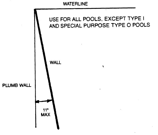
SECTION R326.6.1. Walls shall not be greater than eleven (11) degrees from plumb for a minimum depth of two (2) feet nine (9) inches from the waterline in deep areas or two (2) feet three (3) inches in the shallow areas. Below these depths the wall may be curved to join the floor. An exception to this section is walls on Type 1 and special purpose pools shall be plumb as is shown in Section R326.10.9, Figure R326.10(5).
SECTION R326.7 FLOOR SLOPE.
SECTION R326.7.1. Floor slopes shall be in compliance with the following:
1. All slopes shall be uniform.
2. The slope of the floor from the shallow end wall towards the deep end shall not exceed one (1) foot in seven (7) feet (1:7) to the point of the first slope change.
3. The point of the first slope change shall be:
3.1. defined as the point at which the floor slope exceeds one (1) foot in seven (7) feet (1:7); and
3.2. not less than six (6) feet from the shallow end wall.
4. The slope of the floor from the point of the first slope change to the deep end wall shall not exceed one (1) foot in three (3) feet (1:3).
SECTION R326.8 WATER DEPTH.
SECTION R326.8.1. Water depths at the shallow end of the swimming area shall be two (2) feet nine (9) inches minimum and three (3) feet six (6) inches maximum, except for special purpose pools.
SECTION R326.8.2. No minimum water depth shall be specified in a nonswimming area. The nonswimming area shall be visually set apart.
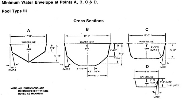
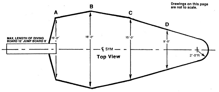
SECTION R326.8.3. Pools of the type where manufactured diving equipment is permitted shall have the area and depth of water in compliance with the drawings for Type I through Type V pools.
SECTION R326.8.4. Where manufactured diving equipment is installed, it shall:
1. conform to the specifications set forth in Section R326.15; and
2. be so located in the diving area of the pool so as to provide the minimum dimensions for area and depth of water as shown on drawings of Type I through Type V pools.
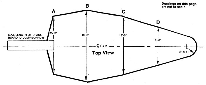
SECTION R326.8.5. The tip of the manufactured diving equipment shall be located at point "A", which is the reference point for all other dimensions.
SECTION R326.9 MINIMUM VERTICAL CLEARANCES.
SECTION R326.9.1. Minimum unobstructed headroom from the top of the manufactured diving equipment shall be provided for diving in accordance with Table R326.9.1 unless greater dimensions are called for by the manufacturer.
| TABLE R326.9.1 | |
| POOL TYPE | MINIMUM HEADROOM ABOVE BOARD |
| I | 12 feet |
| II | 12 feet |
| III | 12 feet |
| IV | 13 feet |
| V | 14 feet |
SECTION R326.10 POOL TYPES
SECTION R326.10.1. Residential pools shall be further classified into types as an indication of the suitability of a pool for use with diving equipment as shown in Section R326.10.2, Figure R326.10(1). Diving equipment classified at a higher type shall not be used on a pool of a lesser type.
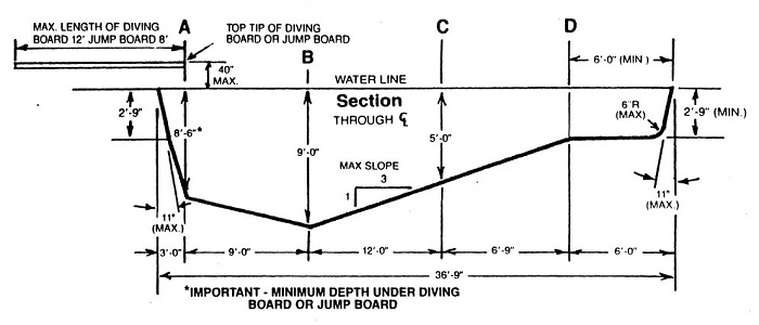
SECTION R326.10.2. This section contains Figure R326.10(1), a reference chart of minimum dimensions for residential pools with manufactured diving equipment.
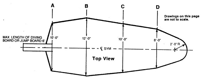
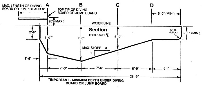
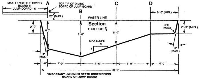
| FIGURE R326.10(1) |
| MINIMUM DIMENSIONS FOR RESIDENTIAL POOLS WITH DIVING EQUIPMENT |
| (LONGITUDINAL CROSS-SECTION AT CENTERLINE) |
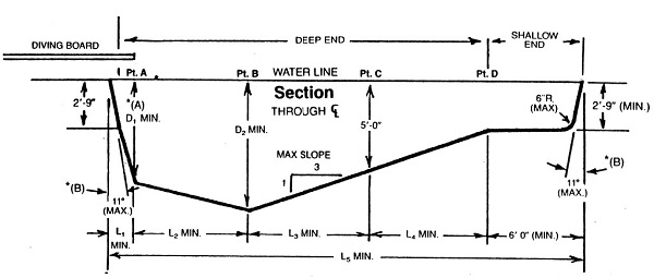
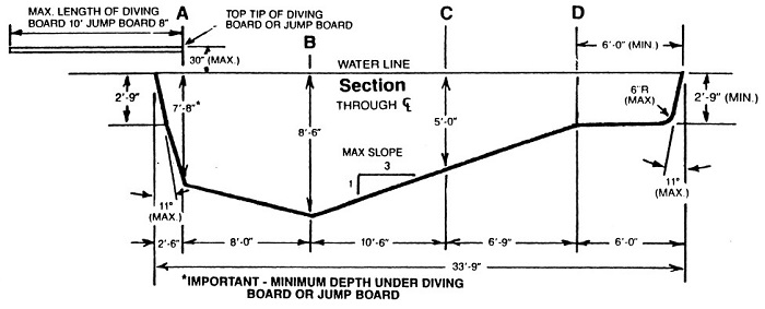
*(A) Minimum depth under diving board or jump board.
*(B) Type I pools shall have plumb walls as shown in Section R326.10.9, Figure R326.10(5).
| POOL TYPE | MINIMUM DIMENSIONS | MINIMUM WIDTH OF POOL | ||||||||
| D1 | D2 | L1 | L2 | L3 | L4 | L5 | PT. A | PT. B | PT. C | |
| 0 | * | * | * | * | * | * | * | * | * | * |
| I | 6'-0" | 7'-6" | 1'-6" | 7'-0" | 7'-6" | 6'-9" | 28'-9" | 10'-0" | 12'-0" | 10'-0" |
| II | 6'-0" | 7'-6" | 1'-6" | 7'-0" | 7'-6" | 6'-9" | 28'-9" | 12'-0" | 15'-0" | 12'-0" |
| III | 6'-10" | 8'-0" | 2'-0" | 7'-6" | 9'-0" | 6'-9" | 31'-3" | 12'-0" | 15'-0" | 12'-0" |
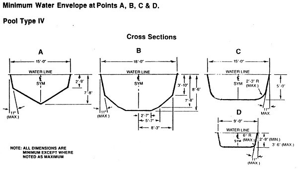
| IV | 7'-8" | 8'-6" | 2'-6" | 8'-0" | 10'-6" | 6'-9" | 33'-9" | 15'-0" | 18'-0" | 15'-0" |
| V | 8'-6" | 9'-0" | 3'-0" | 9'-0" | 12'-0" | 6'-9" | 36'-9" | 15'-0" | 18'-0" | 15'-0" |
| *Diving equipment is prohibited. | ||||||||||
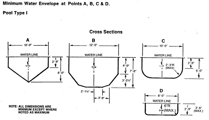
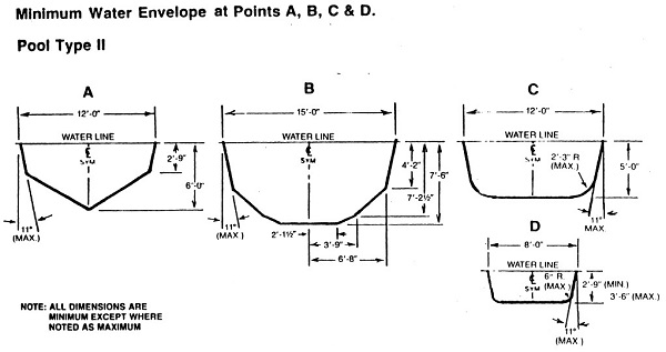
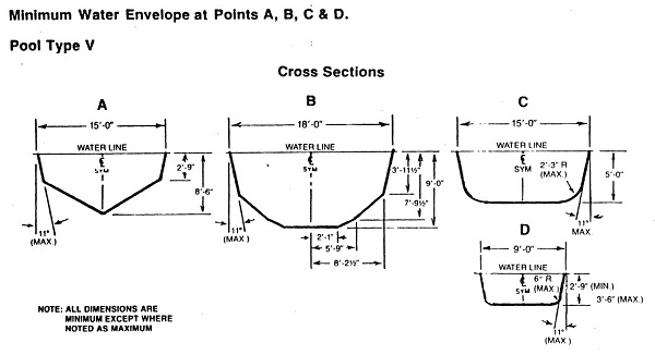
SECTION R326.10.3. The minimum allowable underwater cross sections at B, C, and D shall be as shown on drawings of Type I through Type V pools (Section R326.10.9 through Section R326.10.13, Figure R326.10(5) through Figure R326.10(9)).
SECTION R326.10.4. Constant depth and other swimming pools on which diving equipment is prohibited (Type 0) with water depths not exceeding four (4) feet shall not be limited in width, length, or depth of water except as provided in Section R326.5 and Section R326.6.
SECTION R326.10.5. Stationary diving platforms built on-site shall be located in the diving area of the pool so as to provide the minimum dimension as shown in Figure R326.10(1), at a maximum height of three (3) feet above the waterline. Point "A" shall be eighteen (18) inches in front of the wall at the platform center line. Stationary diving platforms shall not extend more than eighteen (18) inches horizontally over the water from the wall.
SECTION R326.10.6. This section contains Figure R326.10(2), a maximum allowable wall slope.
| FIGURE R326.10(2) |
| MAXIMUM ALLOWABLE WALL SLOPE |
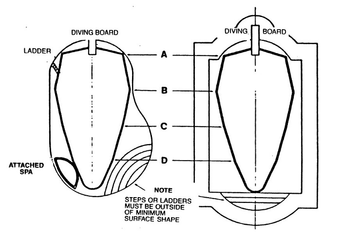
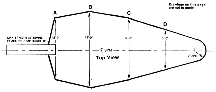
SECTION R326.10.7. This section contains Figure R326.10(3), relationship of minimum top view dimensions to steps or stairs.
| FIGURE R326.10(3) |
| MINIMUM TOP VIEW DIMENSIONS TO STEPS OR STAIRS |
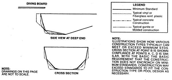
SECTION R326.10.8. This section contains Figure R326.10(4), relationship of vinyl, fiberglass, gunite, and concrete construction to minimum requirements.
| FIGURE R326.10(4) |
| RELATIONSHIP OF VINYL, FIBERGLASS, GUNITE, AND CONCRETE CONSTRUCTION TO MINIMUM REQUIREMENTS |
SECTION R326.10.9. This section contains Figure R326.10(5), minimum dimensions for a Type I pool.
| FIGURE R326.10(5) |
| MINIMUM DIMENSIONS FOR A TYPE I POOL |
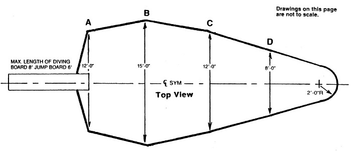
SECTION R326.10.10. This section contains Figure R326.10(6), minimum dimensions for a Type II pool.
| FIGURE R326.10(6) |
| MINIMUM DIMENSIONS FOR A TYPE II POOL |
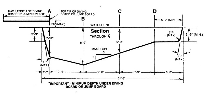
SECTION R326.10.11. This section contains Figure R326.10(7), minimum dimensions for a Type III pool.
| FIGURE R326.10(7) |
| MINIMUM DIMENSIONS FOR A TYPE III POOL |
SECTION R326.10.12. This section contains Figure R326.10(8), minimum dimensions for a Type IV pool.
| FIGURE R326.10(8) |
| MINIMUM DIMENSIONS FOR A TYPE IV POOL |
SECTION R326.10.13. This section contains Figure R326.10(9), minimum dimensions for a Type V pool.
| FIGURE R326.10(9) |
| MINIMUM DIMENSIONS FOR A TYPE V POOL |
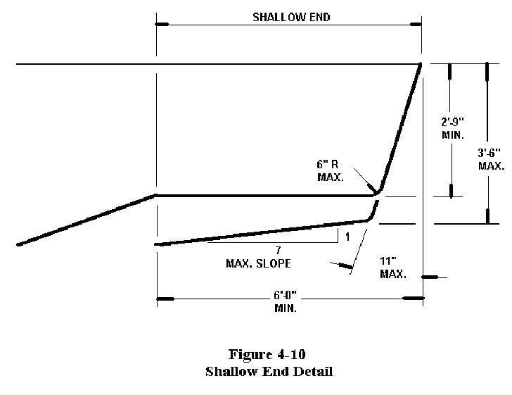
SECTION R326.10.14. This section contains Figure R326.10(10), shallow end detail for pool Types II through V.
| FIGURE R326.10(10) |
| SHALLOW END DETAIL FOR POOL TYPES II THROUGH V |
SECTION R326.11 OFFSET LEDGES AND UNDERWATER SEAT BENCHES.
SECTION R326.11.1. Offset ledges, when provided, shall fall within eleven (11) degrees from plumb starting at the junction of the pool wall and waterline and shall have a slip-resisting surface. Maximum width shall be eight (8) inches. The typical allowable dimensions are based on the depths shown as follows:
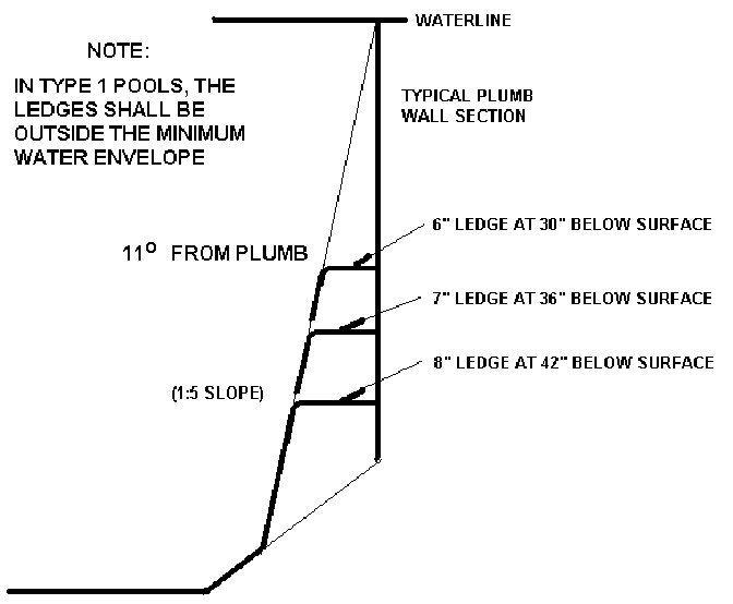
SECTION R326.11.2. Underwater seat benches, where provided, shall:
1. have a maximum horizontal seat bench depth of twenty (20) inches below the waterline;
2. be visually set apart;
3. have a slip-resisting surface; and
4. be located fully outside of the required minimum diving water envelope if the pool is designed for use with manufactured diving equipment.
Underwater seat benches shall be permitted in the deep end of the pool only if they are either completely recessed, shaped to be compatible with the slope of the pool wall, or in a corner of the pool.
SECTION R326.12 DECKS AND DECK EQUIPMENT
SECTION R326.12.1. Deck work shall be designed and installed so as to include the quality of subbase, concrete mix design, reinforcing, joints, and finishes. Work performed in accordance with the recommended practices of the American Concrete Institute (ACI) Standard 302.1R-80, "Guide for Concrete Floor and Slab Construction", may be deemed acceptable.
SECTION R326.12.2. Decks, ramps, coping, and similar step surfaces shall be slip-resisting and easily cleanable.
SECTION R326.12.3. Special features in or on decks such as markers, brand insignias, or similar features shall conform to this section.
SECTION R326.12.4. Steps outside the pool perimeter are not required to comply with the provisions of Section R326, but shall be constructed in accordance with all other applicable provisions of this code.
SECTION R326.12.5. Excavation areas shall be adequately compacted when they support the deck or decks.
SECTION R326.12.6. Decks shall be sloped to effectively drain either to perimeter areas or to deck drains. Drainage shall remove pool splash water, deck cleaning water, and rainwater without leaving standing water.
SECTION R326.12.7. The minimum slope of decks shall be:
1. one-eighth (1/8) inch per one (1) foot (1/8:12) for textured, hand-finished concrete decks;
2. one-fourth (1/4) inch per one (1) foot (1/4:12) for exposed aggregate concrete decks; and
3. one-half (1/2) inch per one (1) foot (1/2:12) for indoor/outdoor carpeting decks.
SECTION R326.12.8. The maximum slope for all decks other than wood decks shall be one (1) inch per foot except for ramps. The maximum slope for wood decks shall be one-eighth (1/8) inch per foot except for ramps. Expansion gaps shall be based on good engineering practices with respect to the type of wood used.
SECTION R326.12.9. The maximum voids between adjoining concrete slabs, and between concrete slabs and expansion joint material, shall be three-sixteenths (3/16) inch of horizontal clearance with a maximum difference in vertical elevation of one-fourth (1/4) inch.
SECTION R326.12.10. Construction joints where pool coping meets concrete decks shall be watertight and shall not allow water to pass to the ground beneath.
SECTION R326.12.11. The areas where the decks join pool coping shall be designed and installed so as to protect the coping and its mortar bed from damage as a result of reasonable movement of adjoining decks.
SECTION R326.12.12. Joints in decks shall be provided to minimize the potential for cracks due to a change in elevations, separation of surfaces, or movement of the slab.
SECTION R326.12.13. The areas where decks join concrete work shall be protected by expansion joints to protect the pool adequately from the pressures of relative movements.
SECTION R326.12.14. Decks shall be edged, have a radius, or be otherwise relieved to eliminate sharp corners.
SECTION R326.12.15. Site drainage shall be provided so as to direct all perimeter deck drainage as well as general site and roof drainage away from the pool.
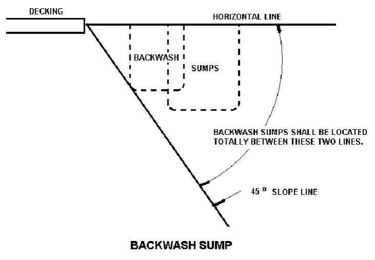
SECTION R326.12.16. If used, an open pit or leaching design for backwash sump purposes shall be located so that it falls completely below adjacent decks and fully outside a line projected forty-five (45) degrees downward and away from such decks as shown below.
SECTION R326.13 CIRCULATION PIPING.
SECTION R326.13.1. Circulation system piping, other than that integrally included in the manufacture of the pool, shall be subject to an induced static hydraulic pressure test (sealed system) at twenty-five (25) pounds per square inch for thirty (30) minutes. This test shall be performed before the deck is poured, and the pressure shall be maintained through the deck pour.
SECTION R326.13.2. Valves installed in or under any decks shall provide a minimum ten (10) inches diameter access cover and valve pit to facilitate servicing.
SECTION R326.13.3. A hose bibb with a vacuum breaker shall be provided for washing down the entire deck area.
SECTION R326.14 POOL EGRESS.
SECTION R326.14.1. All pools shall have a means of entry/exit in the shallow end consisting of one (1) ladder, stairs, or recessed treads. Where two (2) or more entries/exits are used, the ladders, stairs, or recessed treads may be used in combination. All treads shall have slip-resisting surfaces.
SECTION R326.14.2. Where water depths are twenty-four (24) inches or less at the pool wall, the areas shall be considered as providing their own natural mode for entry/exit.
SECTION R326.14.3. For pools over thirty (30) feet in width, both sides of the deep portions of the pool shall have entries/exits provided.
SECTION R326.14.4. A means of entry/exit for the shallow end shall be located between the shallow end wall and the cross section at point "D". Where required, entry/exit for the deep end shall be between the deep end wall and the cross section at point "B". (Refer to Section R326.10.2, Figure R326.10(1))
SECTION R326.14.5. Ladders, stairs, recessed treads, or underwater seat benches shall be provided at the deep end of the pool if the water depth is over five (5) feet.
SECTION R326.14.6. The design and construction of protruding and recessed pool stairs shall conform to the following:
1. Step treads shall have a minimum unobstructed horizontal depth of ten (10) inches and a minimum unobstructed surface area of two hundred forty (240) square inches.
2. Risers at the center line of the treads shall have a maximum uniform height of twelve (12) inches with the bottom riser height allowed to vary plus or minus two (2) inches from the uniform riser height.
3. The vertical distance between the pool coping edge, deck, or step surface, which shall be slip-resisting, and the uppermost step tread shall be a maximum of twelve (12) inches.
SECTION R326.14.7. If handrails are used with stairs, they shall conform to the following:
1. Handrails, if removable, shall be installed in such a way that they cannot be removed without the use of tools.
2. The leading edge of handrails facilitating stairs and pool entry/exit shall be not more than eighteen (18) inches plus or minus three (3) inches horizontally from the vertical plane of the bottom riser, where applicable.
3. The outside diameter of handrails shall be between one (1) inch and two (2) inches.
SECTION R326.14.8. Underwater seats or benches may be provided as part of the stairs or recessed treads.
SECTION R326.14.9. The design and construction of pool ladders shall conform to the following:
1. Pool ladders shall be made entirely of corrosion-resistant materials.
2. Ladders shall provide two (2) handholds or two (2) handrails.
3. Below the water level, there shall be a clearance of not more than six (6) nor less than three (3) inches between any ladder tread edge measured from the pool wall side of the tread and the pool wall.
4. The clear distance between ladder handrails shall be a minimum of seventeen (17) inches and a maximum of twenty-four (24) inches.
5. There shall be a uniform height between ladder treads with a seven (7) inch minimum distance and a twelve (12) inch maximum distance.
6. Ladder treads shall have a minimum horizontal depth of one and one-half (1 1/2) inches.
7. The vertical distance between the top tread and the pool coping or deck shall be a maximum of twelve (12) inches.
SECTION R326.14.10. The design and construction of recessed treads in the pool wall shall conform to the following:
1. Recessed treads at the center line shall have a uniform vertical spacing of twelve (12) inches maximum and seven (7) inches minimum.
2. The vertical distance between the pool coping edge, deck, or step surface and the uppermost recessed tread shall be a maximum of twelve (12) inches.
3. Recessed treads shall have a minimum depth of five (5) inches and a minimum width of twelve (12) inches.
4. Recessed treads shall drain into the pool to prevent accumulation of dirt.
5. Each set of recessed treads shall be provided with a pair of handrails, grab rails, or handholds to serve all treads and risers.
SECTION R326.15 DIVING EQUIPMENT.
SECTION R326.15.1. Supports, platforms, stairs, and ladders for manufactured diving equipment shall be designed to carry the anticipated loads. Stairs and ladders shall be of corrosion-resistant material, easily cleanable, and with slip-resisting tread. All manufactured diving stands higher than twenty-one (21) inches measured from the deck to the top butt end of the board shall be provided with stairs or a ladder, or both. Step treads shall be self-draining.
SECTION R326.15.2. Platforms and manufactured diving equipment of one (1) meter or higher shall be protected with guard rails, which shall be at least thirty (30) inches above the diving board and extend to the edge of the pool wall.
SECTION R326.15.3. Manufactured diving equipment shall be:
1. designed for swimming pool use; and
2. installed in accordance with the manufacturer's recommendations provided with the equipment.
SECTION R326.15.4. A label shall be permanently affixed to the manufactured diving equipment or jump board and shall include not less than the:
1. manufacturer's name and address;
2. board equipment length;
3. identification as to diving or jump board;
4. fulcrum setting specifications, if applicable;
5. date of manufacture; and
6. reference to manufacturer's safety standard, if any, that the board will meet.
SECTION R326.15.5. Manufactured diving equipment suitable for installation on a lower pool type may be installed on any higher pool type providing no less a water envelope is provided from the tip of the board than called for in the lower type. Manufactured diving equipment of a greater type, for example, Type III, shall not be installed on a pool of lesser type, for example, Type II. In addition, the following provisions apply:
1. Manufactured diving equipment shall have slip-resisting tread surfaces.
2. Manufactured diving equipment shall be permanently anchored to the pool deck. The edge of the board at the tip end shall be level with the water surface. The tip end of the board over the pool water surface may be higher than the butt end of the board. Refer to manufacturer's recommendations.
SECTION R326.16 SWIMMING POOL SLIDES.
SECTION R326.16.1. Swimming pool slides shall meet the requirements of 16 CFR 1207, Safety Standard for Swimming Pool Slides as published by the U.S. Consumer Product Safety Commission, 4330 East-West Highway, Bethesda, Maryland 20814. Slides, where provided for use with swimming pools, and shall have a permanent label or separate certificate indicating conformance with the rules of the Consumer Product Safety Commission contained at 16 CFR 1207.
SECTION R326.16.2. Swimming pool slides in residential swimming pools shall terminate such that the following applies:
1. The end of the slide is not more than twelve (12) inches above the pool deck.
2. The depth of the water at the end of the slide meets the manufacturer's recommendations or thirty-six (36) inches, whichever is greater.
3. The distance from the end of the slide is not less than twenty (20) feet measured along the axis of travel.
4. The depth of water described in item 2, or a gradually increasing depth, shall be maintained for not less than ten (10) feet beyond the end of the slide. This depth of water may gradually decrease beyond that point to a minimum water depth of twenty-four (24) inches. For this requirement a maximum slope of one (1) in seven (7) (1:7) shall be considered "gradual".
SECTION R326.16.3. Swimming pool slides shall be installed in accordance with the manufacturer's installation instructions and specifications.
SECTION R326.17 CIRCULATION SYSTEM.
SECTION R326.17.1. A circulation system consisting of pumps, piping, return inlets and suction outlets, filters, and other necessary equipment shall be provided for complete circulation of water through all parts of the pool. This circulation system shall be capable of maintaining water clarity and chemistry requirements.
SECTION R326.17.2. The equipment shall be of adequate size to turn over the entire pool water capacity at least once every twelve (12) hours. Water clarity shall be maintained. When standing at the pool's edge at the deep end, the deepest portion of the pool floor shall be visible.
SECTION R326.17.3. Circulation system components that require replacement or servicing shall be:
1. accessible for inspection, repair, or replacement; and
2. installed according to the manufacturer's instructions.
SECTION R326.17.4. Pool equipment shall be:
1. properly supported to prevent damage from misalignment, settlement, and other causes; and
2. mounted so as to minimize the potential for the accumulation of debris and moisture following manufacturer's instructions.
SECTION R326.17.5. The water velocity in the pool piping shall not exceed ten (10) feet per second for discharge piping and eight (8) feet per second for suction piping, unless summary calculations are provided to show that the greater flow is possible with the pump and piping provided. In copper pipes, the velocity shall not exceed eight (8) feet per second for suction and discharge piping. Pool piping shall be sized to permit the rated flows for filtering.
SECTION R326.17.6. The circulation system piping and fittings shall be:
1. nontoxic;
2. considered to be process piping; and
3. of material able to withstand operating pressures and operating conditions.
SECTION R326.17.7. Equipment shall be designed and fabricated to drain the pool water from the equipment, together with exposed face piping, by removal of drain plugs and manipulating valves, or by other methods. Refer to manufacturer's recommendations for specific information on draining the system.
SECTION R326.17.8. A pressure or vacuum gauge or other means of indicating system conditions shall be provided in the circulation system in an easily readable location.
SECTION R326.17.9. Time clocks may be used to set the operating period of the circulation system. When time clocks are used, they shall also govern the operating time of appurtenant devices such as chemical or disinfectant feeders, slurry feeders, heaters, or similar devices, that are dependent upon circulation pump flow.
SECTION R326.17.10. Written operation and maintenance instructions shall be provided for the circulation system.
SECTION R326.18 FILTERS.
SECTION R326.18.1. Filters shall be designed so that after cleaning per manufacturer's instructions the system can provide the water clarity noted in Section R326.17.1.
SECTION R326.18.2. Filters shall be designed so that filtration surfaces can be inspected and serviced.
SECTION R326.18.3. On pressure-type filters, a means shall be provided to permit the release of internal pressure.
SECTION R326.18.4. Any filter incorporating an automatic internal air release as its principal means of air release shall have lids that provide a slow and safe release of pressure as a part of its design.
SECTION R326.18.5. Any separation tank used in conjunction with any filter tank shall have a manual means of air release or a lid that provides a slow and safe release of pressure as it is opened as a part of its design.
SECTION R326.18.6. Pressure filters and separation tanks shall:
1. have operation and maintenance instructions permanently installed on the filter or separation tank; and
2. include a precautionary statement warning not to start up the system after maintenance without first opening the air release and proper reassembly of the filter and separation tank.
The statement shall be visible and noticeable within the area of the air release.
SECTION R326.18.7. Piping furnished with the filter shall be of suitable material capable of withstanding one and one-half (1 1/2) times the working pressure. The suction piping shall not collapse when there is a complete shutoff of flow on the suction side of the pump.
SECTION R326.19 PUMPS.
SECTION R326.19.1. A pump and motor shall be provided for circulation of the pool water. Performance of all pumps shall meet or exceed the conditions of flow required for filtering, cleaning, if applicable, and the filters against the total dynamic head developed by the complete system.
SECTION R326.19.2. With all pressure filter systems a cleanable strainer or screen shall be provided upstream of the circulation pumps to remove solids, debris, hair, lint, and other similar items.
SECTION R326.19.3. Pumps and motors shall be accessible for inspection and service.
SECTION R326.19.4. The design and construction of the pumps and component parts shall provide safe operation that is not hazardous to the operator or maintenance personnel.
SECTION R326.19.5. Where a mechanical pump seal is provided, components of the seal shall be corrosion-resistant and capable of operating under conditions normally encountered in pool operation.
SECTION R326.19.6. Proper direction of rotation for the pump shall be clearly indicated on the pump.
SECTION R326.19.7. All motors shall:
1. have as a minimum an open drip-proof enclosure; and
2. be constructed electrically and mechanically to perform satisfactorily and safely under the conditions of load and environment normally encountered in swimming pool installations.
SECTION R326.19.8. Motors shall be capable of operating the pumps under full load with a voltage variation of plus or minus ten percent (10%) from the nameplate rating. If the maximum service factor of the motor is exceeded (at full voltage), the manufacturer shall indicate this on the pump curve.
SECTION R326.19.9. All motors shall have thermal or current overload protection, either built-in or in the line starter, to provide locked rotor and running protection.
SECTION R326.19.10. Where the pump is below the waterline, valves shall be installed on permanently connected suction and discharge lines, located in an accessible place outside the walls of the pool, where they shall be readily and easily accessible for maintenance and removal of the pump.
SECTION R326.20 RETURN INLETS AND SUCTION OUTLETS.
SECTION R326.20.1. Return inlets and suction outlets shall be provided and arranged to produce a uniform circulation of water and maintain a uniform disinfectant residual throughout the entire pool. Where skimmers are used, the return inlets shall be located so as to help bring floating particles within range of the skimmers.
SECTION R326.20.2. The number of return inlets shall be based on a minimum of one (1) return inlet per six hundred (600) square feet of pool surface area, or fraction thereof. Return inlet fittings shall be installed of sufficient pipe size or quantity to allow a full design turnover rate of the circulation system in accordance with the manufacturer's recommendations for return inlets.
SECTION R326.20.3. Return inlets from the circulation system shall be designed so as not to constitute a hazard to the bather.
SECTION R326.20.4. The pool shall not be operated if the suction outlet grate is missing, broken, or secured in such a way that it can be removed without the use of tools.
SECTION R326.20.5. If the suction outlet system, such as a filtration system, booster system, automatic cleaning system, solar system, or other similar system, has a single suction outlet, or multiple suction outlets that can be isolated by valves, each suction outlet shall protect against bather entrapment by:
1. an antivortex cover;
2. a twelve (12) inch by twelve (12) inch (12 × 12) grate or larger; or
3. other means acceptable to the local authority.
SECTION R326.20.6. Where provided, the vacuum cleaner fittings shall be located in accessible positions at least six (6) inches and not greater than eighteen (18) inches below the minimum operating water level or as an attachment to the skimmers.
SECTION R326.21 SURFACE SKIMMER SYSTEMS.
SECTION R326.21.1. A surface skimming system shall be:
1. provided on all residential swimming pools; and
2. designed and constructed to skim the pool surface when the water level is maintained within the operational parameters of the system's rim or weir device.
SECTION R326.21.2. Skimming devices shall be designed and installed so as not to constitute a hazard to the bather.
SECTION R326.21.3. Where automatic surface skimmers are used as the sole overflow system, at least one (1) surface skimmer shall be provided for each eight hundred (800) square feet or fraction thereof of the water surface area. Nominal recessed areas such as stairs and spas, shall not be considered in the calculation. Where skimmers are used, they shall be located to maintain effective skimming action over the entire surface of the pool.
SECTION R326.22 ELECTRICAL REQUIREMENTS.
SECTION R326.22.1. The requirements of 675 IAC 17 , the Indiana Electrical Code, shall be followed in the installation of all electrical equipment wiring or appliances in the pool area or vicinity of the pool's circulation system, for all in-ground, on-ground, and therapeutic residential swimming pools, and ornamental fountains. Construction and installation of electric wiring and equipment associated with all spas, hot tubs, and hydromassage bathtubs, whether permanently installed or storable, shall comply with requirements of Chapter 42 of this code.
SECTION R326.23 HEATERS.
SECTION R326.23.1. Swimming pool heaters shall be of an "approved" type.
SECTION R326.23.2. Heaters shall be properly sized.
SECTION R326.23.3. The heaters shall be installed according to the manufacturer's recommendations, but not less than the following:
1. The heater shall be installed on a concrete (or equivalent) base unless it is specifically designed for installation on a combustible surface.
2. When installing the heater, adequate clearances shall be maintained on all sides and over the top of the unit. Consult manufacturer's instructions for proper clearances.
3. In order to ensure proper combustion, the heater shall have adequate ventilation installed as follows:
3.1. When installing a heater indoors, proper openings to the room are required. The heater shall be installed in accordance with 675 IAC 18 , the Indiana Mechanical Code, and the manufacturer's recommendations for properly sized air openings to the enclosure.
3.2. All fossil fuel heaters shall be supplied with some type of venting system for either indoor or outdoor installation. These draft or venting devices shall be installed according to the manufacturer's recommendations and shall not be modified.
3.3. When installing a heater that will be using propane gas, special precautions shall be noted. Propane gas is heavier than air and, therefore, can create special problems when the heater is installed in a pit or in an enclosed area. Whenever installing a heater with propane gas, the manufacturer's ventilation recommendations shall be followed.
SECTION R326.23.4. The heater gas supply and pipe sizing shall:
1. be adequate; and
2. comply with manufacturer's recommendations.
When installing a gas-fired heater, the gas line shall be run from the gas meter as directly as practical.
SECTION R326.23.5. The heater circulation system shall comply with the manufacturer's recommendations. Precautions shall be taken to avoid siphonage of hot water into the pump or filter. When manufacturers recommend metal pipe, that is, copper and heat sinks, they shall be installed vertically connected to the heater to prevent heat damage to plastic circulation pipe. Heater piping shall be designed to avoid excessive friction losses through the pipe or bypass valves, or both, as required. When installing bypass valves, caution shall be taken to ensure adequate flow through the heater at all times.
SECTION R326.23.6. The water piping system shall be installed according to the manufacturer's recommendations. When manufacturers recommend precautions to eliminate siphonage so that the heater does not destroy the filter or any plastic pipe that is being used, the manufacturer's recommendations shall be followed. NOTE: When installing a heater and a filter system, adequate provisions shall be made so that the heater does not cause excessive pressure drop to the filter system. Refer to manufacturer's requirements or recommendations, or both, for installation of bypass valves. Excessive flow that causes pressure drop can be eliminated by the installation of an external or an automatic bypass valve. When installing a bypass valve, caution shall be noted so that there is always adequate flow through the heater.
SECTION R326.23.7. A time clock is recommended, and when used it shall be set long enough to properly filter the water and allow enough time for proper heating of the pool. It is recommended that a dual time clock or fireman's switch be used in conjunction with the heater to shut the heater off approximately one-half (1/2) hour before the filter system shuts down.
SECTION R326.24 WATER SUPPLY.
SECTION R326.24.1. The water supply serving the pool, which may come from a variety of sources, shall meet 327 IAC , the rules of the environmental rules board, before the bather uses the pool.
SECTION R326.24.2. No direct mechanical connection shall be made between the potable water supply and the swimming pool, chlorinating equipment, or the system of piping for the pool unless it is protected against backflow and siphonage in a manner approved by 675 IAC 16 , the Indiana Plumbing Code, or through an air gap meeting that same code.
SECTION R326.24.3. An over-the-rim spout, if used, shall be located under a diving board, adjacent to a ladder, or otherwise properly shielded so as not to create a hazard. Its open end shall:
1. have no sharp edges; and
2. not protrude more than two (2) inches beyond the edge of the pool.
SECTION R326.25 WASTEWATER DISPOSAL.
SECTION R326.25.1. Backwash water shall be discharged into a sanitary sewer through an approved air gap or into an approved subsurface disposal system or by other means in accordance with 675 IAC 16 , the Indiana Plumbing Code, and 327 IAC , the rules of the environmental rules board.
SECTION R326.26 DISINFECTANT; OXIDATION; CHEMICAL FEEDER REQUIREMENT.
SECTION R326.26.1. Disinfectant equipment, oxidation equipment, and chemical feeders, hereafter referred to jointly as "equipment", shall be capable of precisely introducing a sufficient quantity of an approved disinfecting agent or other chemical to maintain one (1) milligram per liter of free chlorine residual.
SECTION R326.26.2. Manufacturer's instructions shall be used in installing chemical feeders. The installation and use of chemical feeders shall conform to the following:
1. Where using chemical feeders, it is extremely important that they be installed downstream from the filter and heater. An exception is equipment specifically labeled for feeding to the suction side of the pump.
2. If the chemical feeder is equipped with its own pump, it shall be installed so it introduces the gas or solution downstream from the heater and, if possible, at a position lower than the heater outlet fitting.
3. Chemical feed pumps shall be wired so they cannot operate unless the filter pump is running. If the chlorinator has an independent timer, the filter and chemical feed pump timers shall be interlocked.
4. A check valve shall be installed in the piping between the heater and the point of chemical feed.
SECTION R326.26.3. The installation of ozone generating equipment shall be limited to low ozone output generating equipment. The installation and use of ozone generating equipment shall conform to the following:
1. Installation of ozone generating equipment shall allow for indications of operation or malfunction to be easily observed. The equipment shall be installed in a manner such that a malfunction will not endanger operators or pool users.
2. Ozone generating equipment shall be used in conjunction with other chemical treatments to meet the chemical operating parameters in this section. Normal maintenance and monitoring of water chemistry shall be followed.
3. If the equipment is capable of exposing maintenance or service personnel to ozone concentrations exceeding five hundred (500) parts per million, a self-contained breathing apparatus approved for ozone usage shall be provided. If a distinct, pungent odor is smelled when the ozone generating equipment is operating, the equipment shall be shut down, and the area shall be ventilated. The equipment shall be inspected and repaired as necessary by qualified service personnel.
4. Manufacturer's recommendations shall be used to determine where and how ozone shall be injected.
SECTION R326.27 SAFETY FEATURES.
SECTION R326.27.1. A residential pool shall be provided with a suitable handhold around its perimeter in areas where depths exceed three (3) feet six (6) inches. Handholds shall be provided no farther apart than four (4) feet and shall consist of any one (1) or a combination of items listed as follows:
1. Coping, ledge, or deck along the immediate top edge of the pool that provides a slip-resisting surface of at least four (4) inches minimum horizontal width and located at or not more than twelve (12) inches above the waterline.
2. Ladders, stairs, or seat ledges.
3. A secured rope or railing placed at or not more than twelve (12) inches above the waterline.
SECTION R326.27.2. Rope anchor devices shall be installed at a minimum of one (1) foot and a maximum of two (2) feet on the shallow end side of a point of change in floor slope. In pools where the slope change occurs in water depths less than four (4) feet six (6) inches, a transition rope supported by buoys shall be installed.
SECTION R326.27.3. Access to residential pools shall be restricted by one (1) of the following means:
1. Walls or fencing not less than four (4) feet high and completely surrounding the pool and deck area with the exception of self-closing and latching gates and doors, both capable of being locked.
2. Other means not less than four (4) feet high and deemed impenetrable by the enforcing authority at the time of construction and completely surrounding the pool and deck area when the pool is not in use.
3. A combination of item 1 and item 2 that completely surrounds the pool and deck with the exception of self-closing and latching gates and doors which are capable of being locked. This applies to item 1, item 2, and this item only.
4. A power safety pool cover that:
4.1. shall provide a continuous connection between the cover and the deck, so as to prohibit access to the pool when the cover is completely drawn over the pool;
4.2. shall be mechanically operated such that the cover cannot be drawn open or retracted without the use of a:
4.2.1. key; or
4.2.2. key and switch; or
4.2.3. touch pad with a personal access code;
4.3. is installed with track, rollers, rails, guides, or other accessories necessary to accomplish item 4.1 and item 4.2, in accordance with the manufacturer's instructions; and
4.4. shall bear an identification tag indicating that the cover satisfies the requirements of ASTM F 1346–91 (2018), Standards Performance Specification for Safety Covers and Labeling Requirements for All Covers for Swimming Pools, Spas, and Hot Tubs, as published by ASTM International, 100 Barr Harbor Drive, P.O. Box C700, West Conshohocken, Pennsylvania 19428-2959 for power safety pool covers.
SECTION R326.27.4. Not less than the following lifesaving equipment shall be installed with each residential swimming pool:
1. A ring or throwing buoy fitted with forty (40) feet of one-fourth (1/4) inch diameter line.
2. A pole not less than twelve (12) feet in length.
3. Access to a telephone.
675 IAC 14-4.4-39 Section R401.3; drainage
Authority:
Sec. 39. Delete the first sentence of the text of SECTION R401.3 without substitution.
(Fire Prevention and Building Safety Commission;
675 IAC 14-4.4-40 Section R403.1; general
Authority:
Sec. 40. Delete the word "continuous" in the first sentence of the text of SECTION R403.1 without substitution.
(Fire Prevention and Building Safety Commission;
675 IAC 14-4.4-41 Table R403.4; minimum depth (D) and width (W) of crushed stone footingsa, b (inches)
Authority:
Sec. 41. Change the title of TABLE R403 to read as follows: TABLE R403.4 MINIMUM DEPTH (D) AND WIDTH (W) OF CRUSHED STONE FOOTINGSa, b (inches).
(Fire Prevention and Building Safety Commission;
675 IAC 14-4.4-42 Section R403.1.1.1; size of footings supporting piers and columns
Authority:
Sec. 42. Add SECTION R403.1.1.1 to read as follows: SECTION R403.1.1.1 SIZE OF FOOTINGS SUPPORTING PIERS AND COLUMNS. Size of footings supporting piers and columns shall comply with TABLE R403.2.
(Fire Prevention and Building Safety Commission;
675 IAC 14-4.4-43 Section R403.1.4.1; frost protection
Authority:
Sec. 43. Change SECTION R403.1.4.1 as follows:
(Fire Prevention and Building Safety Commission;
(1) Change the text of SECTION R403.1.4.1 to read as follows:
Except where otherwise protected from frost, foundation walls, piers, and other permanent supports of buildings and structures shall be protected from frost by one or more of the following methods:
1. Extended below the frost line specified in Table R301.2(1).
2. Constructed in accordance with Section R403.3.
3. Constructed in accordance with ASCE 32.
4. Erected on solid rock.
Footings shall not bear on frozen soil unless the frozen condition is permanent.
(2) Change the EXCEPTIONS of SECTION R403.1.4.1 to read as follows:
1. Protection of freestanding accessory structures with an area of 721 square feet (67 m2) or less shall not be required when constructed in accordance with TABLE R309.
2. Decks not supported by a dwelling need not be provided with footings that extend below the frost line.
675 IAC 14-4.4-44 Section R403.1.6; foundation anchorage
Authority:
Sec. 44. Delete SECTION R403.1.6 and substitute to read as follows:
(Fire Prevention and Building Safety Commission;
SECTION R403.1.6 FOUNDATION ANCHORAGE.
Wood sole plates and sill plates supported directly on concrete slab, and concrete and masonry walls, shall be anchored to the foundation in accordance with this section. Sill plates and sole plates shall be protected against decay and termites where required by Sections R317 and R318. Cold-formed steel framing shall be anchored directly to the foundation or fastened to wood sill plates anchored to the foundation in accordance with Section R505.3.1 or R603.3.1, as applicable. Wood sill plates supporting cold-formed steel framing shall be anchored to the foundation in accordance with this section.
SECTION R403.1.6.1 ANCHOR BOLTS.
Anchor bolts shall be located in the center one-third of the plate, shall have at least seven (7) inches (178 mm) embedment into concrete or grouted masonry cells, and shall have at least one and one half (1 1/2) inches (38.7 mm) of concrete or grout surrounding the bolt shaft. Each anchor bolt shall have a washer, sized to be at least two times the diameter of the hole it covers, and a nut tightened to the plate. Except as allowed otherwise in this section anchor bolts shall be no farther than twelve (12) inches (305 mm) from corners.
EXCEPTION: Approved anchors or anchor straps spaced as required to provide equivalent anchorage to 1/2 inch diameter (12.7 mm) anchor bolts.
SECTION R403.1.6.2 SOLE PLATE ANCHOR BOLT LOCATION.
Anchor bolts spaced a maximum of six (6) feet (1,829 mm) on center shall fasten wood sole plates of exterior walls and braced wall panels at building interiors, when installed directly on concrete slab foundations. There shall be no fewer than two bolts per plate section with one bolt located not more than twelve (12) inches (305 mm) or less than seven bolt diameters from each end of the plate section.
EXCEPTIONS:
1. Sole plates twenty-four (24) inches (610 mm) total length or shorter supporting offset braced wall panels shall be anchored to the foundation with no fewer than one anchor bolt located in the center third of the plate section and shall be attached to adjacent braced wall panels at corners as shown in item 9 of Table R602.3(1).
2. Connection of walls twelve (12) inches (305 mm) total length or shorter connecting offset braced wall panels to the foundation without anchor bolts shall be permitted. The wall shall be attached to adjacent braced wall panels at corners as shown in item 9 of Table R602.3(1).
3. Sole plates of interior bearing wall panel sections on concrete slab foundation that are not part of a braced wall panel shall be positively anchored with approved fasteners.
SECTION R403.1.6.3 SILL PLATE ANCHOR BOLT LOCATION.
Anchor bolts shall fasten sill plates to concrete floors a maximum of 6 feet (1,829 mm) on center. Anchor bolts shall fasten sill plates to the top of concrete or masonry walls a maximum of 4 feet (1,219 mm) on center.
EXCEPTION: Sill plate anchor bolts shall be spaced a maximum of 6 feet (1,829 mm) on center when installed on foundation walls retaining less than 7 feet (2,135 mm) of unbalanced fill.
SECTION R403.1.6.4 FOUNDATION ANCHORAGE IN SEISMIC DESIGN CATEGORIES C, D0, D1, and D2.
In addition to the requirements of Section R403.1.6, the following requirements shall apply to wood light-frame structures in Seismic Design Categories D0, D1, and D2 and wood light-frame townhouses in Seismic Design Category C.
1. Plate washers conforming to Section R602.11.1 shall be provided for all anchor bolts over the full length of required braced wall lines except where approved anchor straps are used. Properly sized cut washers shall be permitted for anchor bolts in wall lines not containing braced wall panels.
2. Interior braced wall plates shall have anchor bolts spaced at not more than 6 feet (1,829 mm) on center and located within 12 inches (305 mm) of the ends of each plate section where supported on a continuous foundation.
3. Interior bearing wall sole plates shall have anchor bolts spaced at not more than 6 feet (1,829 mm) on center and located within 12 inches (305 mm) of the ends of each plate section where supported on a continuous foundation.
4. The maximum anchor bolt spacing shall be 4 feet (1,219 mm) for buildings over two stories in height.
5. Stepped cripple walls shall conform to Section R602.11.2.
6. Where continuous wood foundations in accordance with Section R404.2 are used, the force transfer shall have a capacity equal to or greater than the connections required by Section R602.11.1, or the braced wall panel shall be connected to the wood foundations in accordance with the braced wall panel-to-floor fastening requirements of Table R602.3(1).
675 IAC 14-4.4-45 Section R403.1.7.3; foundation elevation
Authority:
Sec. 45. Delete SECTION R403.1.7.3 in its entirety without substitution.
(Fire Prevention and Building Safety Commission;
675 IAC 14-4.4-46 Table R403.2; size of footings supporting piers and columns
Authority:
Sec. 46. Add TABLE R403.2 to read as follows:
| TABLE R403.2 | ||||||
| SIZE OF FOOTINGS SUPPORTING PIERS AND COLUMNS | ||||||
| Spacing of Girder "S"1 | Type of Loading2 | Column Size Required3 | Size of Plain Concrete Footing Required3 | |||
| A | B | C | Steel | Wood | ||
| 10' | 5'–6" | – | – | 3" Steel Pipe4 | 4" × 4" | 2' × 2' × 8" 5 |
| 15' | 4'–0" | – | – | |||
| 20' | – | – | – | |||
| 10' | 8'–6" | 5'–0" | – | |||
| 15' | 6'–0" | 4'–0" | – | |||
| 20' | 4'–6" | – | – | |||
| 10' | 12'–0" | 9'–0" | 8'–0" | 6" × 6" | 4' × 4' × 16" 5 | |
| 15' | 10'–0" | 8'–0" | 7'–0" | |||
| 20' | 8'–0" | 7'–0" | 6'–0" | |||
| 10' | 16'–0" | 12'–6" | 11'–0" | 8" × 8" | 4'3" × 4'3" × 17" 5 | |
| 15' | 13'–6" | 10'–6" | 10'–0" | |||
| 20' | 12'–0" | 9'–6" | 8'–0" | |||
| 10' | 20'–0" | 16'–0" | 13'–6" | |||
| 15' | 17'–0" | 13'–6" | 11'–6" | |||
| 20' | 15'–0" | 12'–0" | 10'–0" | |||
| 1The spacing "S" is the tributary load in the girder. It is found by adding the unsupported spans of the floor joists on each side that are supported by the girder and dividing by 2. | ||||||
| 2Figures under type of loading columns are the allowable girder span. | ||||||
| Type A loading is for a girder supporting 1 floor and a roof. | ||||||
| Type B loading is for a girder supporting 2 floors and a roof. | ||||||
| Type C loading is for a girder supporting 3 floors and a roof. | ||||||
| 3Required size of column is based on girder support from 2 sides. Size of footing is based on allowable soil pressure of 2,000 pounds per square foot. | ||||||
| 4Schedule 40. | ||||||
| 5Footing thickness is based on the use of plain concrete with an ultimate compressive strength of not less than 2,000 pounds per square inch at 28 days. If approved, the footing thickness may be reduced based on an engineered design utilizing higher strength concrete or reinforcement. | ||||||
675 IAC 14-4.4-47 Table R404.1.2(8); minimum vertical reinforcement for 6, 8, 10, and 12 inch nominal flat basement wallsb, c, d, e, f, h, i, k, n, o
Authority:
Sec. 47. Delete TABLE R404.l.2(8) in its entirety without substitution.
(Fire Prevention and Building Safety Commission;
675 IAC 14-4.4-48 Section R404.1.3.2; reinforcement for foundation walls
Authority:
Sec. 48. Change the text of SECTION R404.1.3.2 to read as follows:
(Fire Prevention and Building Safety Commission;
Concrete foundation walls shall be laterally supported at the top and bottom. Horizontal reinforcement shall be provided in accordance with Table R404.1.2(1). Vertical reinforcement shall be provided in accordance with Table R404.1.2(2), R404.1.2(3), R404.1.2(4), R404.1.2(5), R404.1.2(6), or R404.1.2(7). Vertical reinforcement for flat basement walls retaining 4 feet (1,219 mm) or more of unbalanced backfill is permitted to be determined in accordance with Table R404.1.2(9). For basement walls supporting above-grade concrete walls, vertical reinforcement shall be the greater of that required by Tables R404.1.2(2) through R404.1.2(7) or by Section R608.6 for the above-grade wall. In buildings assigned to seismic design category D0, D1, or D2, concrete foundation walls shall also comply with Section R404.1.4.2.
675 IAC 14-4.4-49 Section R404.1.3.3.7.2; location of reinforcement in wall
Authority:
Sec. 49. Change the text of SECTION R404.1.3.3.7.2 to read as follows:
(Fire Prevention and Building Safety Commission;
The center of vertical reinforcement in basement walls determined from Tables R404.1.2(2) through R404.1.2(7) shall be located at the centerline of the wall. Regardless of the table used to determine vertical wall reinforcement, the center of the steel shall not vary from the specified location by more than the greater of 10 percent of the wall thickness and 3/8 inch (10 mm). Horizontal and vertical reinforcement shall be located in foundation walls to provide the minimum cover required by Section R404.1.3.3.7.4.
675 IAC 14-4.4-50 Section R404.2.1; identification
Authority:
Sec. 50. Change the text of SECTION R404.2.1 to read as follows:
(Fire Prevention and Building Safety Commission;
Load-bearing lumber shall be identified by the grade mark of a lumber grading or inspection agency that has been approved by an accreditation body that complies with DOC PS 20. Wood structural panels shall conform to DOC PS 1 or DOC PS 2 and shall be identified by a grade mark.
675 IAC 14-4.4-51 Section R405.2.3; drainage system
Authority:
Sec. 51. Change the text of SECTION R405.2.3 to read as follows:
(Fire Prevention and Building Safety Commission;
In other than Group I soils, a sump pit shall be provided to drain the porous layer and footings. The sump pit shall be a minimum of 18 inches (457 mm) in diameter or equivalent and a minimum of 24 inches (610 mm) below the bottom of the basement floor. Where a porous layer of gravel, crushed stone, or coarse sand is used between the soil and the concrete floor slab, openings shall be made in the sump pit to allow drainage of that layer. The sump pit shall be capable of positive gravity or mechanical drainage to remove any accumulated water.
EXCEPTION: When a gravity drain system is used a sump pit is not required.
675 IAC 14-4.4-52 Section R407.3; structural requirements
Authority:
Sec. 52. Change the text of SECTION R407.3 to read as follows:
(Fire Prevention and Building Safety Commission;
The columns shall be restrained to prevent lateral displacement at the bottom end and attached to framing at the top. Wood columns shall be not less in nominal size than 4 inches by 4 inches (102 mm by 102 mm). Steel columns shall be not less than 3 inch diameter (76 mm) Schedule 40 pipe manufactured in accordance with ASTM A53 Grade B or approved equivalent.
EXCEPTION: In seismic design categories A, B, and C, columns not more than 48 inches (1,219 mm) in height on a pier or footing are exempt from the bottom end lateral displacement requirement within under-floor areas enclosed by a continuous foundation.
675 IAC 14-4.4-53 Section R408.1; ventilation
Authority:
Sec. 53. Change the text of the last sentence of SECTION R408.1 to read as follows: One such ventilation opening shall be within 4 feet (1,219 mm) of the inside of each corner of the building.
(Fire Prevention and Building Safety Commission;
675 IAC 14-4.4-54 Section R408.3; unvented crawlspace
Authority:
Sec. 54. Change SECTION R408.3 as follows:
(Fire Prevention and Building Safety Commission;
(1) Delete the text of ITEM 2.1 of SECTION R408.3 and substitute to read as follows:
2.1. The walls of the under-floor space are insulated in accordance with Chapter 11 and Section R316 of this code. Uninsulated mechanical ductwork is allowed and shall have no openings into the under-floor space. A hard surface pad with dimensions of at least 16 inches (407 mm) by 16 inches (407 mm) and an electrical receptacle shall be located adjacent to the sump or gravity drain to allow for the installation of dehumidification equipment in the event of high humidity conditions in the under-floor space.
(2) Delete the text of ITEM 2.2 of SECTION R408.3 and substitute to read as follows:
2.2. The walls of the under-floor space are insulated in accordance with Chapter 11 and Section R316 of this code with insulation materials listed for the interior of a dwelling, or the materials shall be protected in accordance with their listing. A concrete floor at least 2 inches (51 mm) thick installed over a vapor retarder complying with item 1 of this section shall be installed on the ground surface of the under-floor space. Conditioned air shall be circulated through the under-floor space at a rate of at least 1 cfm (0.03 m3) for each 50 square feet (4.6 m2) of under-floor space.
(3) Delete the text of ITEM 2.4 of SECTION R408.3 and substitute to read as follows:
Construction of the crawlspace area shall be in accordance with Section R703.8.6 and Figure R703.8.6(1). The crawlspace perimeter walls are insulated in accordance with Chapter 11 and Section R316 of this code, and insulated or uninsulated ductwork supplies conditioned air to the crawlspace area.
675 IAC 14-4.4-55 Section R408.4; access
Authority:
Sec. 55. Change SECTION R408.4 as follows:
(Fire Prevention and Building Safety Commission;
(1) Delete the text of the second to last sentence of SECTION R408.4 without substitution.
(2) Add an EXCEPTION to the end of SECTION R408.4 to read as follows:
EXCEPTION: Access may be placed under a doorway, provided the step or steps that cover the opening to the crawlspace are attached to the structure at the top with a fixed pin-type hinge, so that, when the step or steps are in the raised position, passage by way of the doorway is restricted.
675 IAC 14-4.4-56 Section R408.8; under-floor drainage
Authority:
Sec. 56. Add SECTION R408.8 to read as follows:
(Fire Prevention and Building Safety Commission;
SECTION R408.8 UNDER-FLOOR DRAINAGE.
Under-floor spaces shall comply with Section R408.3, item 1, and shall be drained to a gravity discharge or sump pit, having a minimum size of 18 inches (457 mm) diameter by 24 inches (610 mm) deep, by one of the following methods:
1. The under-floor space shall be graded at a slope of not less than 1 inch (25 mm) for each 10 feet (3,048 mm) to a gravity discharge or a sump pit installed below the lowest point of the slope so that, in the event of excess water accumulation, a sump pump can be readily installed.
2. The under-floor space shall be graded at a slope of not less than 1/2 inch (13 mm) for each 10 feet (3,048 mm) to a gravity discharge or a sump pit installed below the lowest point of the slope. Not less than 3 inches (76 mm) of granular material shall be placed between the ground surface and the vapor retarder so that, in the event of excess water accumulation, a sump pump can be readily installed.
675 IAC 14-4.4-57 Section R502.1.1; sawn lumber
Authority:
Sec. 57. Delete the text of the last sentence of SECTION R502.1.1 without substitution.
(Fire Prevention and Building Safety Commission;
675 IAC 14-4.4-58 Section R502.6.2; joist framing
Authority:
Sec. 58. Change the text of SECTION R502.6.2 to read as follows:
(Fire Prevention and Building Safety Commission;
Joists framing into the side of a wood girder shall be supported by approved framing anchors or on ledger strips not less than nominal 2 inches by 4 inches (51 mm by 102 mm).
675 IAC 14-4.4-59 Figure R502.8; cutting, notching, and drilling
Authority:
Sec. 59. Delete FIGURE R502.8 and substitute to read as follows: FIGURE R502.8:
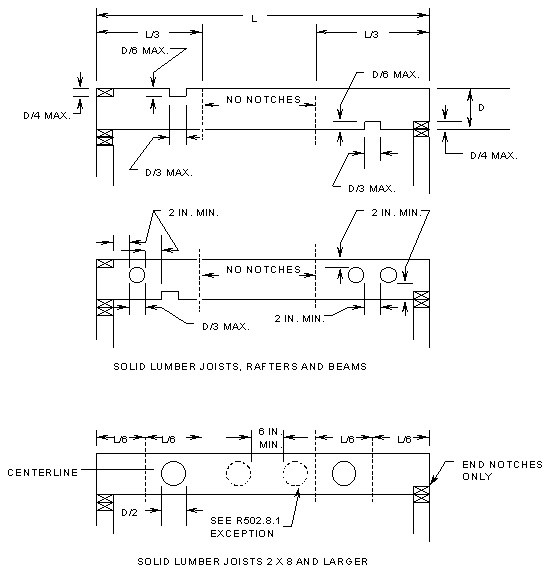
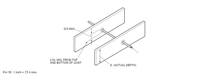
| FIGURE R502.8 |
| CUTTING, NOTCHING, AND DRILLING |
675 IAC 14-4.4-60 Section R502.8.1; sawn lumber (drilling)
Authority:
Sec. 60. Add an EXCEPTION to the end of SECTION R502.8.1 to read as follows:
(Fire Prevention and Building Safety Commission;
EXCEPTION: In 2 x 8 and larger solid lumber joists, holes up to 50 percent of the actual joist depth may be drilled at the center of the joist depth in the second and fifth sixths of the joist span. When the joist spans 90 percent or less of its maximum allowed span per Table R502.3.1(1) or R502.3.1(2), such holes may also be located in the center third of the joist span. Such hole shall be no closer than 6 inches (152 mm) from any other hole. Except for end notches, no notches may be in the same half of the span as a hole allowed by this exception.
675 IAC 14-4.4-61 Table R502.3.3(2); cantilever spans for floor joists supporting exterior balconya, b, e, f, g, h
Authority:
Sec. 61. Add to TABLE R502.3.3(2) as follows:
(Fire Prevention and Building Safety Commission;
(1) Add superscript reference to footnotes "g" and "h" in the title of TABLE R502.3.3(2).
(2) Add footnote "g" to read as follows:
g. In addition to snow loads shown the table includes 40 psf of live load.
(3) Add footnote "h" to read as follows:
h. Use of the table shall be permitted for the construction of interior balconies not supporting roof loads.
675 IAC 14-4.4-62 Section R502.11.1; design (trusses)
Authority:
Sec. 62. Delete the text of the last sentence of SECTION R502.11.1 without substitution.
(Fire Prevention and Building Safety Commission;
675 IAC 14-4.4-63 Section R502.11.4; truss design drawings
Authority:
Sec. 63. Delete the text of SECTION R502.11.4 and substitute to read as follows:
(Fire Prevention and Building Safety Commission;
Truss design drawings shall be provided to the building official as required by the General Administrative Rules (675 IAC 12 ) for Class 1 structures or by local ordinance for Class 2 structures.
675 IAC 14-4.4-64 Section R503.2.1; identification and grade
Authority:
Sec. 64. Change the text of SECTION R503.2.1 to read as follows:
(Fire Prevention and Building Safety Commission;
Wood structural panel sheathing used for structural purposes shall conform to CSA 0325, CSA 0437, DOC PS 1, or DOC PS 2. Panels shall be identified for grade, bond classification, and performance category by a grade mark. The performance category value shall be used as the "nominal panel thickness" or "panel thickness" wherever referenced in this code.
675 IAC 14-4.4-65 Section R503.3.1; identification and grade (particleboard)
Authority:
Sec. 65. Change the text of SECTION R503.3.1 to read as follows:
(Fire Prevention and Building Safety Commission;
Particleboard shall conform to ANSI A208.l and shall be so identified by a grade mark.
675 IAC 14-4.4-66 Section R505.1.3; floor trusses
Authority:
Sec. 66. Change the text of SECTION R505.1.3 to read as follows:
(Fire Prevention and Building Safety Commission;
Cold-formed steel trusses shall be designed, braced, and installed in accordance with AISI S240. In the absence of specific bracing requirements, trusses shall be braced in accordance with accepted industry practices, such as the SBCA Cold-Formed Steel Building Component Safety Information (CFSBCSI), Guide to Good Practice for Handling, Installing & Bracing of Cold-Formed Steel Trusses. Truss members shall not be notched, cut, or altered in any manner without an approved design from a registered design professional.
675 IAC 14-4.4-67 Section R507.2.1; wood materials
Authority:
Sec. 67. Delete the text of the second to last sentence of SECTION R507.2.1 without substitution.
(Fire Prevention and Building Safety Commission;
675 IAC 14-4.4-68 Section R507.4; deck post heighta
Authority:
Sec. 68. Change the text of footnote "a" in TABLE R507.4 to read as follows:
(Fire Prevention and Building Safety Commission;
a. Measured to the underside of the beam from grade, top of column, or post base.
675 IAC 14-4.4-69 Section R507.4.1; deck post to deck footing connection
Authority:
Sec. 69. Change the text of SECTION R507.4.1 to read as follows:
(Fire Prevention and Building Safety Commission;
Where posts bear on concrete footings in accordance with Section R403 and Figure R507.3, lateral restraint shall be provided by manufactured connectors or a minimum post embedment of 12 inches (305 mm) in surrounding soils or concrete piers. Other footing systems shall be permitted.
Exception: Where expansive, compressible, shifting, or other questionable soils are present, surrounding soils shall not be relied on for lateral support.
675 IAC 14-4.4-70 Section R602.1.1; sawn lumber (walls)
Authority:
Sec. 70. Delete the text of the last sentence of SECTION R602.1.1 without substitution.
(Fire Prevention and Building Safety Commission;
675 IAC 14-4.4-71 Table 602.3.2; Single top-plate splice connection details
Authority:
Sec. 71. In Table 602.3.2 change the 3' to 3" in the first and second row of the "Splice plate size" column of the "Corners and intersecting walls" column.
(Fire Prevention and Building Safety Commission;
675 IAC 14-4.4-72 Table 602.7(1); girder spansa and header spansa for exterior bearing walls
Authority:
Sec. 72. Change TABLE R602.7(1) as follows: Delete the three values marked as "12" from the fourth row of Table R602.7(1), directly below the row marked "Building Widthc (feet)", and substitute all three values with the value "20". The fourth row of Table R602.7(1) shall read as follows:
| Building Widthc (feet) | ||||||||
| 20 | 24 | 36 | 20 | 24 | 36 | 20 | 24 | 36 |
675 IAC 14-4.4-73 Section R602.10.9; braced wall panel support
Authority:
Sec. 73. Change the text of ITEM 2 of SECTION R602.10.9 to read as follows:
(Fire Prevention and Building Safety Commission;
2. The capacity of raised floor system post or pier foundations supporting braced wall panels to transmit lateral loads through the floor system and into the foundation shall be designed in accordance with accepted engineering practice.
675 IAC 14-4.4-74 Section R604.1; identification and grade
Authority:
Sec. 74. Change the text of SECTION R604.1 to read as follows:
(Fire Prevention and Building Safety Commission;
Wood structural panels shall conform to DOC PS 1, DOC PS 2, or ANSI/APA PRP 210, CSA O325, or CSA O437. Panels shall be identified by a grade mark.
675 IAC 14-4.4-75 Section R605.1; identification and grade (particleboard)
Authority:
Sec. 75. Delete the words "or certificate of inspection issued by an approved agency" from the text of SECTION R605.1 without substitution.
(Fire Prevention and Building Safety Commission;
675 IAC 14-4.4-76 Section R606.3.5.2; cleanouts
Authority:
Sec. 76. Change the text of SECTION R606.3.5.2 to read as follows:
(Fire Prevention and Building Safety Commission;
Provisions shall be made for cleaning the space to be grouted. Mortar that projects more than 1/2 inch (12.7 mm) into the grout space and any other foreign matter shall be removed from the grout space prior to grouting. Cleanouts shall be provided in the bottom course of masonry for each grout pour where the grout pour height exceeds 64 inches (1,626 mm). In solid grouted masonry, cleanouts shall be spaced horizontally not more than 32 inches (813 mm) on center. The cleanouts shall be sealed before grouting and after inspection.
675 IAC 14-4.4-77 Section R702.7.2; material vapor retarder class
Authority:
Sec. 77. Change the text of SECTION R702.7.2 to read as follows:
(Fire Prevention and Building Safety Commission;
The vapor retarder class shall be based on the manufacturer's certified testing or a tested assembly. The following shall be deemed to meet the class specified:
1. Class I: Sheet polyethylene, unperforated aluminum foil.
2. Class II: Kraft-faced fiberglass batts.
3. Class III: Latex or enamel paint.
675 IAC 14-4.4-78 Table R703.8.4(1); tie attachment and airspace requirements
Authority:
Sec. 78. Change TABLE R703.8.4(1) to read as follows:
| TABLE R703.8.4(1) | ||||
| TIE ATTACHMENT AND AIRSPACE REQUIREMENTS | ||||
| BACKING AND TIE | MINIMUM TIE | MINIMUM TIE FASTENERa | AIRSPACEc | |
| Wood stud backing with corrugated sheet metal | 22 U.S. gage (0.0299 in.) × 7/8 in. wide | 8d common nailb (2 1/2 in. × 0.131 in.) | 3/4 in. minimum between sheathing and veneer | |
| Wood stud backing with metal strand wire | W1.7 (No. 9 U.S. gage; 0.148 in.) with hook embedded in mortar joint | 8d common nailb (2 1/2 in. × 0.131 in.) | 3/4 in. minimum between sheathing and veneer | Maximum 4 1/2 in. between backing and veneer |
| Cold-formed steel stud backing with adjustable metal strand wire | W1.7 (No. 9 U.S. gage; 0.148 in.) with hook embedded in mortar joint | No. 10 screw extending through the steel framing a minimum of three exposed threads | 3/4 in. minimum between sheathing and veneer | Maximum 4 1/2 in. between backing and veneer |
| For SI: 1 inch = 25.4 mm. | ||
| a. In seismic design category D0, D1, or D2, the minimum tie fastener shall be an 8d ring-shank nail (2 1/2 in. × 0.131 in.) or a No. 10 screw extending through the steel framing a minimum of three exposed threads. | ||
| b. All fasteners shall have rust-inhibitive coating suitable for the installation in which they are being used, or be manufactured from material not susceptible to corrosion. | ||
| c. Mortar is permitted to encroach into the airspace or make incidental contact with the sheathing or the sheathing paper or equivalent. | ||
675 IAC 14-4.4-79 Section R703.8.6; drained cavity
Authority:
Sec. 79. Delete SECTION R703.8.6 in its entirety and substitute to read as follows:
SECTION R703.8.6 DRAINED CAVITY.
The 3/4 inch (19 mm) air cavity shall be drained to the exterior of the structure at intervals of not more than 33 inches (838 mm) on center. Each drain shall be not less than 3/16 inch (4.8 mm) in diameter, located immediately above the flashing. For dwellings with crawlspaces, the air cavity may be drained as shown in FIGURE R703.8.6(1). For dwellings with basements, the air cavity may be drained as shown in FIGURE R703.8.6(2).
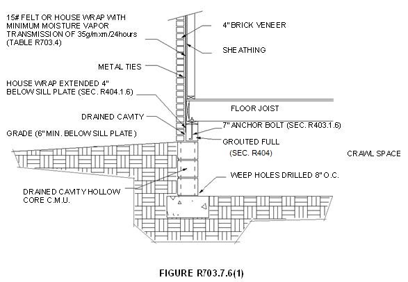
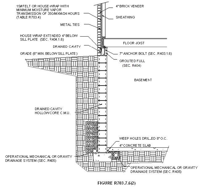
675 IAC 14-4.4-80 Section R802.1.1; sawn lumber
Authority:
Sec. 80. Change the text of SECTION R802.1.1 to read as follows:
(Fire Prevention and Building Safety Commission;
Sawn lumber shall be identified by a grade mark of an accredited lumber grading or inspection agency and have design values certified by an accreditation body that complies with DOC PS 20.
675 IAC 14-4.4-81 Section R802.10.1; truss design drawings
Authority:
Sec. 81. Change the text of the first sentence of SECTION R802.10.1 to read as follows:
(Fire Prevention and Building Safety Commission;
Truss design drawings shall be provided to the building official as required by the General Administrative Rules (675 IAC 12 ) for Class 1 structures or by local ordinance for Class 2 structures.
675 IAC 14-4.4-82 Section R803.2.1; identification and grade
Authority:
Sec. 82. Delete the words "or certificate of inspection issued by an approved agency" from the text of SECTION R803.2.1 without substitution.
(Fire Prevention and Building Safety Commission;
675 IAC 14-4.4-83 Section R806.1; ventilation required
Authority:
Sec. 83. Add an EXCEPTION to SECTION R806.1 to read as follows:
(Fire Prevention and Building Safety Commission;
EXCEPTION: Mechanical ventilation is permitted provided the following conditions are met:
1. The installation complies with manufacturer's instructions.
2. A humidistat is included with the installation.
3. An ammeter or equivalent device is installed in a readily visible location.
675 IAC 14-4.4-84 Section R902.4 rooftop-mounted photovoltaic panel systems
Authority:
Sec. 84. Delete the text of the last sentence of SECTION R902.4 without substitution.
(Fire Prevention and Building Safety Commission;
675 IAC 14-4.4-85 Section R905.2.6; attachment
Authority:
Sec. 85. Delete the words "approved" from the text of SECTION R905.2.6 without substitution.
(Fire Prevention and Building Safety Commission;
675 IAC 14-4.4-86 Section R905.2.8; flashing
Authority:
Sec. 86. Delete the word "approved" from the text of SECTION R905.2.8 without substitution.
(Fire Prevention and Building Safety Commission;
675 IAC 14-4.4-87 Section R905.2.8.4; other flashing
Authority:
Sec. 87. Delete the word "printed" from the text of SECTION R905.2.8.4 without substitution.
(Fire Prevention and Building Safety Commission;
675 IAC 14-4.4-88 Figure R1003.9; termination
Authority:
Sec. 88. Add FIGURE R1003.9 after SECTION R1003.9 as follows:
| FIGURE R1003.9 TERMINATION |
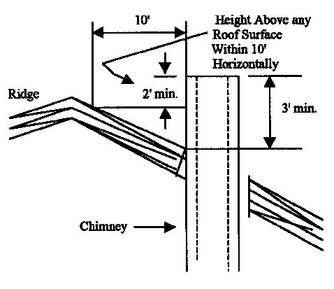
675 IAC 14-4.4-89 Section N1101.5; construction documents
Authority:
Sec. 89. Delete SECTION N1101.5 and SECTION N1101.5.1 and substitute to read as follows:
(Fire Prevention and Building Safety Commission;
SECTION N1101.5 CONSTRUCTION DOCUMENTS.
Energy conservation construction documents shall be submitted for Class 1 structures as required by the General Administrative Rules (675 IAC 12-6 ) and for Class 2 structures as required by local ordinance.
675 IAC 14-4.4-90 Section N1101.6; defined terms
Authority:
Sec. 90. Change SECTION N1101.6 as follows:
(Fire Prevention and Building Safety Commission;
(1) Change the definition of HEATED SLAB in SECTION N1101.6 to read as follows:
HEATED SLAB. Slab-on-grade construction in which the heating elements, hydronic tubing, or hot air distribution system is in contact with, or placed within the slab.
(2) Change the definition of RESIDENTIAL BUILDING in SECTION N1101.6 to read as follows:
RESIDENTIAL BUILDING. For this chapter, includes detached one and two family dwellings, townhouses, applicable Class 1 structures, and their accessory structures.
675 IAC 14-4.4-91 Table N1102.1.2; insulation and fenestration requirements by componenta
Authority:
Sec. 91. Delete TABLE N1102.1.2 and substitute to read as follows:
| TABLE N1102.1.2 | |||||||||
| INSULATION AND FENESTRATION REQUIREMENTS BY COMPONENTa | |||||||||
| CLIMATE ZONE | FENESTRATION U-FACTOR | SKYLIGHT U-FACTORb | CEILING R-VALUE | WOOD FRAME R-VALUE | MASS WALL R-VALUEg | FLOOR R-VALUE | BASEMENT WALL R-VALUEc | SLAB R-VALUE AND DEPTHd | CRAWL SPACE R-VALUE |
| 4 | 0.35 | 0.60 | 38 | 15 | 5/10 | 19 | 10/13 | 10; 2 feet | 10/13 |
| 5 | 0.35 | 0.60 | 38 | 20 or 13+5f | 13/17 | 30e | 10/13 | 10; 2 feet | 10/13 |
a. R-values are minimums. U-factors are maximums. Batts compressed into a framing cavity such that the R-value is reduced by R-1 or more shall be marked with the compressed batt R-value in addition to the full thickness R-value.
b. The fenestration U-factor column excludes skylights.
c. The first R-value applies to continuous insulation, the second to framing cavity insulation; either insulation meets the requirement.
d. Minimum of R-5 shall be provided under the full slab area of heated slabs in addition to the required slab edge insulation R-value for slab as indicated in the table. The slab edge insulation for heated slabs shall not be required to extend below the slab.
e. R-30 or insulation sufficient to fill the framing cavity, R-19 minimum.
f. "13+5" means R-13 cavity insulation with an additional R-5 insulated sheathing applied to the exterior of the wall. If structural sheathing covers 25% or less of the exterior, R-5 sheathing is not required where structural sheathing is used. If structural sheathing covers more than 25% of exterior, structural sheathing shall be supplemented with insulated sheathing of at least R-2.
g. The second R-value applies when more than half the insulation is on the interior.
675 IAC 14-4.4-92 Table N1102.1.4; equivalent U-factorsa
Authority:
Sec. 92. Delete TABLE N1102.1.4 and substitute to read as follows:
| TABLE N1102.1.4 | ||||||||
| EQUIVALENT U-FACTORSa | ||||||||
| CLIMATE ZONE | FENESTRATION U-FACTOR | SKYLIGHT U-FACTOR | CEILING U-FACTOR | FRAME WALL U-FACTOR | MASS WALL U-FACTORb | FLOOR U-FACTOR | BASEMENT WALL U-FACTOR | CRAWL SPACE WALL U-FACTOR |
| 4 | 0.35 | 0.60 | 0.030 | 0.082 | 0.141 | 0.047 | 0.059 | 0.065 |
| 5 | 0.35 | 0.60 | 0.030 | 0.067 | 0.082 | 0.033 | 0.059 | 0.065 |
a. Non-fenestration U-factors shall be obtained from measurement, calculation, or an approved source.
b. When more than half the insulation is on the interior, the mass wall U-factors shall be a maximum of 0.10 in zone 4 and the same as the frame wall U-factor (0.057) in zone 5.
675 IAC 14-4.4-93 Table N1102.2.6; steel frame ceiling, wall and floor insulation R-values
Authority:
Sec. 93. Delete TABLE N1102.2.6 and substitute to read as follows:
| TABLE N1102.2.6 | |
| STEEL FRAME CEILING, WALL AND FLOOR INSULATION R-VALUES | |
| WOOD FRAME R-VALUE REQUIREMENTS | COLD-FORMED STEEL EQUIVALENT R-VALUEa |
| Steel Truss Ceilingsa | |
| R-30 | R-38 or R-30 + 3 or R-26 + 5 |
| R-38 | R-49 or R-38 + 3 |
| R-49 | R-38 + 5 |
| Steel Joist Ceilingsb | |
| R-30 | R-38 in 2 × 4 or 2 × 6 or 2 × 8; R-49 in any framing |
| R-38 | R-49 in 2 × 4 or 2 × 6 or 2 × 8 or 2 × 10 |
| Steel Framed Wall | |
| R-13 | R-13 + 5 or R-15 + 4 or R-21 + 3 or R-0 + 10 |
| R-15 | R-11 + 5 or R-13 + 4 or R-21 + 3 or R-0 + 15 |
| R-19 | R-13 + 9 or R-19 + 8 or R-25 + 7 |
| R-21 | R-13 +10 or R-19 + 9 or R-25 + 8 |
| Steel Joist Floor | |
| R-13 | R-19 in 2 × 6 or R-19 + R-6 in 2 × 8 or 2 × 10 |
| R-19 | R-19 + R-6 in 2 × 6 or R-19 + R-12 in 2 × 8 or 2 × 10 |
For SI: 1 inch= 25.4 mm.
a. Cavity insulation R-value is listed first, followed by continuous insulation R-value.
b. Insulation exceeding the height of the framing shall cover the framing.
675 IAC 14-4.4-94 Section N1102.4.1.1; installation
Authority:
Sec. 94. Delete the text of the last sentence of SECTION N1102.4.1.1 without substitution.
(Fire Prevention and Building Safety Commission;
675 IAC 14-4.4-95 Section N1102.4.1.2; verification
Authority:
Sec. 95. Change the title and text of SECTION N1102.4.1.2 to read as follows:
(Fire Prevention and Building Safety Commission;
SECTION N1102.4.1.2 VERIFICATION.
The building or dwelling unit shall be visually inspected for verification of compliance with TABLE N1102.4.1.1, or tested and verified as having an air leakage rate of not exceeding five air changes per hour. Testing shall be conducted in accordance with RESNET/ICC 380, ASTM E779, or ASTM E1827 and reported at a pressure of 0.2 inch w.g. (50 Pascals). Where required by the building official, testing shall be conducted by an approved third party. A written report of the results of the test shall be signed by the party conducting the test and provided to the building official. Testing shall be performed at any time after creation of all penetrations of the building thermal envelope. During testing:
1. Exterior windows and doors, fireplace doors, and stove doors shall be closed, but not sealed, beyond the intended weatherstripping or other infiltration control measures.
2. Dampers including exhaust, intake, makeup air, backdraft, and flue dampers shall be closed, but not sealed beyond intended infiltration control measures.
3. Interior doors, where installed at the time of the test, shall be open.
4. Exterior or interior terminations for continuous ventilation systems shall be sealed.
5. Heating and cooling systems, where installed at the time of the test, shall be turned off.
6. Supply and return registers, where installed at the time of the test, shall be fully open.
675 IAC 14-4.4-96 Section N1103.3.1; insulation (prescriptive)
Authority:
Sec. 96. Change the text of SECTION N1103.3.1 to read as follows:
(Fire Prevention and Building Safety Commission;
Supply and return ducts in attics shall be insulated to an R-value of not less than R-8 for ducts 3 inches (76 mm) in diameter and larger and not less than R-6 for ducts smaller than 3 inches (76 mm) in diameter. Supply and return ducts in other portions of the building shall be insulated to not less than R-6 for ducts 3 inches (76 mm) in diameter and larger and to not less than R-4.2 for ducts smaller than 3 inches (76 mm) in diameter.
EXCEPTION: Ducts or portions thereof located completely inside the building thermal envelope.
675 IAC 14-4.4-97 Section N1103.3.3; duct testing (mandatory)
Authority:
Sec. 97. Change the text of SECTION N1103.3.3 to read as follows:
(Fire Prevention and Building Safety Commission;
Ducts shall be pressure tested to determine air leakage by one of the following methods:
1. Rough-in test: Total leakage shall be measured with a pressure differential of 0.1 inch w.g. (25 Pa) across the system, including the manufacturer's air handler enclosure if installed at the time of the test. Registers shall be taped or otherwise sealed during the test.
2. Postconstruction test: Leakage to outside shall be measured with a pressure differential of 0.1 inch w.g. (25 Pa) across the entire system, including the manufacturer's air handler enclosure. Registers shall be taped or otherwise sealed during the test.
EXCEPTIONS:
1. A duct air-leakage test shall not be required where the ducts and air handlers are located entirely within the building thermal envelope.
2. A duct air-leakage test shall not be required for ducts serving heat or energy recovery ventilators that are not integrated with ducts serving heating or cooling systems.
A written report of the results of the test shall be signed by the party conducting the test and provided to the building official.
675 IAC 14-4.4-98 Section N1103.3.4; duct leakage (prescriptive)
Authority:
Sec. 98. Change the text of SECTION N1103.3.4 to read as follows:
(Fire Prevention and Building Safety Commission;
The total leakage of the ducts, where measured in accordance with Section N1103.3.3 (R403.3.3), shall be as follows:
1. Rough-in test: The total leakage shall be less than or equal to 4 cubic feet per minute (113.3 L/min) per 100 square feet (9.29 m2) of conditioned floor area where the air handler is installed at the time of the test. Where the air handler is not installed at the time of the test, the total leakage shall be less than or equal to 3 cubic feet per minute (85 L/min) per 100 square feet (9.29 m2) of conditioned floor area.
2. Postconstruction test: Leakage to outside shall be less than or equal to 4 cubic feet per minute (113.3 L/min) per 100 square feet (9.29 m2) of conditioned floor area.
675 IAC 14-4.4-99 Section N1103.3.5; building cavities (mandatory)
Authority:
Sec. 99. Change the text of SECTION N1103.3.5 to read as follows:
(Fire Prevention and Building Safety Commission;
Building framing cavities shall not be used as supply ducts or plenums.
675 IAC 14-4.4-100 Section N1103.6; mechanical ventilation (mandatory)
Authority:
Sec. 100. Change the text of SECTION N1103.6 to read as follows:
(Fire Prevention and Building Safety Commission;
The building shall be provided with ventilation that complies with the requirements of Section M1505 or with other approved means of ventilation. Outdoor air intakes and exhausts shall have automatic or gravity dampers that close when the ventilation system is not operating.
675 IAC 14-4.4-101 Section N1105.3; performance based compliance
Authority:
Sec. 101. Delete the text of the last sentence of SECTION N1105.3 without substitution. The EXCEPTION of SECTION N1105.3 is retained as written without amendment.
(Fire Prevention and Building Safety Commission;
675 IAC 14-4.4-102 Section N1105.4.2; compliance report
Authority:
Sec. 102. Change the text of SECTION N1105.4.2 to read as follows:
(Fire Prevention and Building Safety Commission;
Compliance software tools shall generate a report that documents that the proposed design complies with Section N1105.3. A compliance report on the proposed design shall be submitted for Class 1 structures as required by the General Administrative Rules (675 IAC 12 ) and as required by local ordinance for Class 2 structures. Upon completion of the building, a compliance report based on the as-built condition of the building shall be submitted to the building official before a certificate of occupancy is issued. Batch sampling of buildings to determine energy code compliance shall only be allowed for stacked multiple-family units.
Compliance reports shall include information in accordance with Sections N1105.4.2.1 and N1105.4.2.2. Where the proposed design of a building could be built on different sites where the cardinal orientation of the building on each site is different, compliance of the proposed design for the purposes of the application for the building permit shall be based on the worst case orientation, worst case configuration, worst case building air leakage, and worst case duct leakage. Such worst case parameters shall be used as inputs to the compliance software for energy analysis.
675 IAC 14-4.4-103 Table N1105.5.2(1); specifications for the standard reference and proposed designs
Authority:
Sec. 103. Change the STANDARD REFERENCE DESIGN specifications for AIR EXCHANGE RATE in TABLE N1105.5.2(1) to read as follows:
| BUILDING COMPONENT | STANDARD REFERENCE DESIGN | PROPOSED DESIGN |
| Air exchange rate | The air leakage rate at a pressure of 0.2 inch w.g. (50 Pa) shall be 5 air changes per hour. | The measured air exchange ratea. |
| The mechanical ventilation rate shall be in addition to the air leakage rate and shall be the same as in the proposed design, but not greater than 0.01 × CFA + 7.5 × (Nbr + 1) | ||
| where: | The mechanical ventilation rateb shall be in addition to the air leakage rate and shall be as proposed. | |
| CFA = conditioned floor area, ft2. | ||
| Nbr = number of bedrooms. | ||
| Energy recovery shall not be assumed for mechanical ventilation. |
675 IAC 14-4.4-104 Section N1107.1; scope
Authority:
Sec. 104. Change the text of SECTION N1107.1 to read as follows:
(Fire Prevention and Building Safety Commission;
The provisions of Sections N1107 through N1111 shall control the alteration, addition and change of occupancy of existing buildings and structures.
675 IAC 14-4.4-105 Section N1107.1.1; additions and alterations: general
Authority:
Sec. 105. Change the title and text of SECTION N1107.1.1 to read as follows:
(Fire Prevention and Building Safety Commission;
SECTION N1107.1.1 ADDITIONS AND ALTERATIONS: GENERAL.
Additions and alterations to an existing building, building system or portion thereof shall comply with Section N1108, N1109, or N1110. Unaltered portions of the existing building or building supply system shall not be required to comply with this chapter.
675 IAC 14-4.4-106 Section N1107.3; maintenance
Authority:
Sec. 106. Change the text of SECTION N1107.3 to read as follows:
(Fire Prevention and Building Safety Commission;
The requirements of this chapter shall not provide the basis for removal or abrogation of energy conservation, fire protection and safety systems, and devices in existing structures.
675 IAC 14-4.4-107 Section N1107.4; compliance
Authority:
Sec. 107. Delete the text of SECTION N1107.4 and substitute to read as follows: Alterations, additions, changes in occupancy, or relocation of existing buildings shall comply with this chapter and the General Administrative Rules (675 IAC 12 ).
(Fire Prevention and Building Safety Commission;
675 IAC 14-4.4-108 Section N1107.5; new and replacement materials
Authority:
Sec. 108. Change the text of SECTION N1107.5 to read as follows:
(Fire Prevention and Building Safety Commission;
Except as otherwise required or permitted by this code, materials permitted by the applicable code for new construction shall be used. Hazardous materials shall not be used where the code for new construction would not allow their use in buildings of similar occupancy, purpose, and location.
675 IAC 14-4.4-109 Section N1107.6; historic buildings
Authority:
Sec. 109. Delete the text of SECTION N1107.6 and substitute to read as follows: See General Administrative Rules (675 IAC 12 ).
(Fire Prevention and Building Safety Commission;
675 IAC 14-4.4-110 Section M1201.1; scope
Authority:
Sec. 110. Change the text of SECTION M1201.1 to read as follows:
(Fire Prevention and Building Safety Commission;
The provisions of Chapters 12 through 24 of this code shall regulate the design, installation, alteration, and inspection of mechanical systems that are permanently installed and used to control environmental conditions within buildings. These chapters shall also regulate those mechanical systems, system components, equipment, and appliances specifically addressed in this code.
675 IAC 14-4.4-111 Section M1201.2; application
Authority:
Sec. 111. Delete SECTION M1201.2 in its entirety without substitution.
(Fire Prevention and Building Safety Commission;
675 IAC 14-4.4-112 Section M1202; application
Authority:
Sec. 112. Delete SECTION M1202 and substitute to read as follows:
(Fire Prevention and Building Safety Commission;
For existing installations see Chapter 1 of this code and the General Administrative Rules (675 IAC 12 ).
675 IAC 14-4.4-113 Section M1301.2; identification
Authority:
Sec. 113. Change the text of SECTION M1301.2 to read as follows:
(Fire Prevention and Building Safety Commission;
Each uncut length of pipe and tubing and each pipe fitting utilized in a mechanical system shall bear the identification of the manufacturer.
675 IAC 14-4.4-114 Section M1302.1; listed and labeled
Authority:
Sec. 114. Change the text of SECTION M1302.1 to read as follows:
(Fire Prevention and Building Safety Commission;
Appliances regulated by this code shall be listed and labeled for the application in which they are installed and used, unless otherwise approved in accordance with Section R106.1.
675 IAC 14-4.4-115 Section M1305.1; appliance access for inspection service, repair, and replacement
Authority:
Sec. 115. Change the text of SECTION M1305.1 to read as follows:
(Fire Prevention and Building Safety Commission;
Appliances shall be located to allow for access for inspection, service, repair, and replacement without removing permanent construction, or any other piping or ducts not connected to the appliance being inspected, serviced, repaired, or replaced. A level working space not less than 30 inches deep and 30 inches wide (762 mm by 762 mm) shall be provided in front of the control side to service an appliance.
675 IAC 14-4.4-116 Section M1305.1.3.1; ground clearance
Authority:
Sec. 116. Change the text of SECTION M1305.1.3.1 to read as follows:
(Fire Prevention and Building Safety Commission;
Equipment and appliances supported from the ground shall be level and firmly supported on a concrete slab or other approved material not less than 2 inches (51 mm) above the finished grade. Such support shall be in accordance with the manufacturer's installation instructions. Appliances suspended from the floor shall have a clearance of not less than 6 inches (152 mm) from the ground.
675 IAC 14-4.4-117 Section M1307.3.1; protection from impact
Authority:
Sec. 117. Delete the text of SECTION M1307.3.1 and substitute to read as follows:
(Fire Prevention and Building Safety Commission;
Building appliances and their appurtenances shall be installed outside the intended vehicle travel path. Vehicle travel path shall be determined by the garage door rough opening width. When building appliances and their appurtenances cannot be installed outside the vehicle travel path due to design and construction restraints, such appliances shall be protected by one of the following methods:
1. Installed in an adjacent but separate equipment room within the garage;
2. Installed in an adjacent equipment alcove within the garage that has a raised floor or platform that is at least twenty-four (24) inches higher than the garage floor;
3. Install bollards that are a minimum three (3) inch diameter schedule forty (40) steel pipe embedded a minimum of eighteen (18) inches below grade and at least twenty-four (24) inches above the garage floor with pipe cap;
4. Install bollards that are a minimum three (3) inch diameter schedule 40 steel pipe with a welded eight (8) inches by eight (8) inches by one-quarter (1/4) inch base plate anchored to the garage floor slab using one-half (1/2) inch wedge anchors or equivalent with a minimum embedment of two and one-fourth (2 1/4) inches. Height of bollard to be at least twenty-four (24) inches above garage floor with pipe cap; or
5. Install a minimum seventy-two (72) inches long by six (6) inches wide by four (4) inches high bumper curb that is anchored to the concrete floor.
675 IAC 14-4.4-118 Section M1411.3.1; auxiliary and secondary drain systems
Authority:
Sec. 118. Add ITEM 5 to SECTION M1411.3.1 to read as follows:
(Fire Prevention and Building Safety Commission;
5. When installed on a water-resistant floor sloped to a floor drain in the same room or space.
675 IAC 14-4.4-119 Section M1502.4.2; duct installation
Authority:
Sec. 119. Change the text of SECTION M1502.4.2 to read as follows:
(Fire Prevention and Building Safety Commission;
Exhaust ducts shall be supported at intervals not to exceed twelve (12) feet (3,658 mm) and shall be secured in place. The insert end of the duct shall extend into the adjoining duct or fitting in the direction of airflow. Exhaust duct joints shall be sealed in accordance with Section M1601.4.1 and shall be fastened mechanically or by other approved methods. Ducts shall not be joined with screws or similar fasteners that protrude more than 1/8 inch (3.2 mm) into the inside of the duct. Where dryer exhaust ducts are enclosed in wall or ceiling cavities, such cavities shall allow the installation of the duct without deformation.
675 IAC 14-4.4-120 Section M1601.1.2; underground duct systems
Authority:
Sec. 120. Change the text of SECTION M1601.1.2 to read as follows:
(Fire Prevention and Building Safety Commission;
Underground duct systems shall be constructed of approved concrete, clay, metal, or plastic. The maximum design temperature for systems utilizing plastic duct and fittings shall be 150°F (66°C). Metal ducts shall be protected from corrosion in an approved manner or shall be completely encased in concrete not less than 2 inches (51 mm) thick. Nonmetallic ducts shall be installed in accordance with the manufacturer's instructions. Plastic pipe and fitting materials shall conform to cell classification 12454-B of ASTM D1248 or ASTM D1784 and external loading properties of ASTM D2412. Ducts shall slope to a drainage point that has access. Ducts shall be sealed according to the manufacturer's installation instructions or Section M1601.4 prior to encasing the ducts in concrete or direct burial. Metallic ducts that have an approved protective coating and nonmetallic ducts shall be installed in accordance with the manufacturer's instructions.
675 IAC 14-4.4-121 Section M1601.4.5; fireblocking
Authority:
Sec. 121. Change the text of SECTION M1601.4.5 to read as follows:
(Fire Prevention and Building Safety Commission;
Duct installations shall be fireblocked in accordance with Section R302.11.
675 IAC 14-4.4-122 Section M1602.2; return air openings
Authority:
Sec. 122. Delete ITEM 6 of SECTION M1602.2 without substitution, and renumber ITEM 7 of SECTION M1602.2 to read as ITEM 6.
(Fire Prevention and Building Safety Commission;
675 IAC 14-4.4-123 Section M1801.9; fireblocking
Authority:
Sec. 123. Change the text of SECTION M1801.9 to read as follows:
(Fire Prevention and Building Safety Commission;
Vent and chimney installations shall be fireblocked in accordance with Sections R302.11 and R1003.19.
675 IAC 14-4.4-124 Section M2001.1.2; regulated boilers
Authority:
Sec. 124. Add SECTION M2001.1.2 to read as follows:
(Fire Prevention and Building Safety Commission;
SECTION M2001.1.2 REGULATED BOILERS.
Boilers and pressure vessels regulated pursuant to IC 22-15-6 are not regulated by this code.
675 IAC 14-4.4-125 Section M2201.3; underground tanks
Authority:
Sec. 125. Delete the text of SECTION M2201.3 and substitute to read as follows:
(Fire Prevention and Building Safety Commission;
Excavations for underground tanks shall not undermine the foundations of existing structures. Underground tanks shall be set on firm foundations and surrounded with at least 6 inches (152.4 mm) of noncorrosive inert material, such as clean sand or gravel well tamped in place or in accordance with the manufacturer's installation instructions. Tanks shall be covered with a minimum of 2 feet (609.6 mm) of earth or shall be covered by not less than 1 foot (304.8 mm) of earth, on top of which shall be placed a slab of reinforced concrete not less than 4 inches (101.6 mm) thick. When underground tanks are, or are likely to be, subjected to traffic, they shall be protected against damage from vehicles passing over them by at least 3 feet (914.4 mm) of earth cover, or 18 inches (457.2 mm) of well-tamped earth plus 6 inches (152.4 mm) of reinforced concrete, or 8 inches (203.2 mm) of asphaltic concrete. When asphaltic or reinforced concrete paving is used as part of the protection, it shall extend at least 1 foot (304.8 mm) horizontally beyond the outline of the tank in all directions. The clearance from the tank to the nearest wall of a basement, pit, or property line shall not be less than 1 foot (305 mm). Corrosion protection shall be provided in accordance with Section M2203.7.
675 IAC 14-4.4-126 Section M2301.1; general
Authority:
Sec. 126. Change the text of SECTION M2301.1 to read as follows:
(Fire Prevention and Building Safety Commission;
This section provides for the design, construction, installation, and alteration of equipment and systems using solar thermal energy to provide space heating or cooling, hot water heating, and swimming pool heating.
675 IAC 14-4.4-127 Section G2401.1; application
Authority:
Sec. 127. Change the second paragraph of the text of SECTION G2401.1 to read as follows:
(Fire Prevention and Building Safety Commission;
Coverage of piping systems shall extend from the point of delivery to the outlet of the appliance shutoff valves (see definition of "point of delivery"). Piping systems requirements shall include design, materials, components, fabrication, assembly, installation, and testing. Requirements for gas appliances and related accessories shall include installation, combustion, and ventilation air and venting and connections to piping systems.
675 IAC 14-4.4-128 Section G2403; general definitions
Authority:
Sec. 128. Change SECTION G2403 as follows:
(Fire Prevention and Building Safety Commission;
(1) Change the title of SECTION G2403 to read as follows:
SECTION G2403 (202) GENERAL DEFINITIONS FOR THE PURPOSE OF CHAPTER 24 ONLY.
(2) Change the definition of APPROVED to read as follows:
APPROVED means, as to materials, equipment, appliances, methods of design, and types of construction, acceptance by the building official by one (1) of the following methods:
(1) investigation or tests conducted by recognized authorities;
(2) investigation or tests conducted by technical or scientific organizations; or
(3) accepted principles.
The investigation, tests, or principles shall establish that the materials, equipment, appliances, methods of design, and types of construction are safe for their intended purpose.
(3) Add a sentence to the end of the definition of BOILER, LOW-PRESSURE to read as follows:
This definition is not applicable to boilers and pressure vessels regulated pursuant to IC 22-15-6 .
(4) Add the following to the end of the definition of MODULATING: NFPA 58. See 675 IAC 22-2.2-14 [675 IAC 22-2.2-14 was repealed filed Mar 18, 2008, 2:30 p.m.: 20080423-IR-675070478FRA , eff 90 days after filing with the Publisher].
675 IAC 14-4.4-129 Section G2404.5; reserved
Authority:
Sec. 129. Change SECTION G2404.5 as follows:
(Fire Prevention and Building Safety Commission;
(1) Change the title of SECTION G2404.5 to read as follows:
SECTION G2404.5 RESERVED.
(2) Delete the text of SECTION G2404.5 without substitution.
675 IAC 14-4.4-130 Section G2404.10; auxiliary drain pan
Authority:
Sec. 130. Change the title "EXCEPTION" in SECTION G2404.10 to read as "EXCEPTIONS", number the first exception as "1.", and add a second exception to SECTION G2404.10 to read as follows: 2. An auxiliary drain pan shall not be required for appliances installed on a water-resistant floor that slopes to a drain.
(Fire Prevention and Building Safety Commission;
675 IAC 14-4.4-131 Section G2405.1; structural safety
Authority:
Sec. 131. Change the text of SECTION G2405.1 to read as follows:
(Fire Prevention and Building Safety Commission;
The building shall not be weakened by the installation of any gas piping. In the process of installing or altering any gas piping, the finished floors, walls, ceilings, tile work, or any other part of the building or premises that is required to be changed or replaced shall be left in a safe structural condition in accordance with the requirements of this code.
675 IAC 14-4.4-132 Section G2408.4; clearances from grade
Authority:
Sec. 132. Change the text of SECTION G2408.4 to read as follows:
(Fire Prevention and Building Safety Commission;
Equipment and appliances installed at grade level shall be supported on a level concrete slab or other approved material extending not less than 2 inches (52 mm) above adjoining grade or shall be suspended not less than 6 inches (152 mm) above adjoining grade. Such supports shall be installed in accordance with the manufacturer's instructions.
675 IAC 14-4.4-133 Section G2411.2.1; point of connection
Authority:
Sec. 133. Change the text of SECTION G2411.2.1 to read as follows:
(Fire Prevention and Building Safety Commission;
The bonding jumper shall connect to a metallic pipe, pipe fitting, or CSST fitting.
675 IAC 14-4.4-134 Section G2411.2.6; separation
Authority:
Sec. 134. Add SECTION G2411.2.6 to read as follows:
(Fire Prevention and Building Safety Commission;
SECTION G2411.2.6 SEPARATION.
Except where connected to appliances and at bonding connections, corrugated stainless steel tubing that is not listed with an arc-resistant jacket or coating system in accordance with ANSI LC1/CSA 6.26 shall be isolated from metal gas piping, metal water piping, metal air ducts, metal structural framing, and all electrical wiring methods by a separation space of at least 2 inches.
675 IAC 14-4.4-135 Section G2412.1; scope
Authority:
Sec. 135. Change the text of SECTION G2412.1 to read as follows:
(Fire Prevention and Building Safety Commission;
This section shall govern the design, installation, and modification of piping systems. The applicability of this code to piping systems extends from the point of delivery to the connections with the appliances and includes the design, materials, components, fabrication, assembly, installation, and testing of such piping systems.
675 IAC 14-4.4-136 Section G2412.9; identification
Authority:
Sec. 136. Change the text of SECTION G2412.9 to read as follows:
(Fire Prevention and Building Safety Commission;
Each uncut length of pipe and tubing and each pipe fitting, utilized in a fuel gas system, shall bear the identification of the manufacturer.
Exceptions:
1. Steel pipe sections that are cut from longer sections of pipe.
2. Steel pipe fittings 2 inches or less in size.
3. Where identification is provided on the product packaging or crating.
4. Where other approved documentation is provided.
675 IAC 14-4.4-137 Section G2414.3; other materials
Authority:
Sec. 137. Change the text of SECTION G2414.3 to read as follows:
(Fire Prevention and Building Safety Commission;
Material not covered by the standards specifications listed herein shall be investigated and tested to determine that it is safe and suitable for the proposed service, and, in addition, shall be recommended for that service by the manufacturer and shall be approved by the building official.
675 IAC 14-4.4-138 Section G2420.2; meter valve
Authority:
Sec. 138. Change the text of SECTION G2420.2 to read as follows:
(Fire Prevention and Building Safety Commission;
Every nonutility owned meter shall be equipped with a shutoff valve located on the supply side of the meter.
675 IAC 14-4.4-139 Section G2422.1; connecting appliances
Authority:
Sec. 139. Change the text of ITEM 2 of SECTION G2422.1 to read as follows:
(Fire Prevention and Building Safety Commission;
2. Corrugated stainless steel tubing (CSST) where installed in accordance with the manufacturer's instructions and when protected from damage by a semirigid sleeve or conduit where it enters the appliance.
675 IAC 14-4.4-140 Section G2425.1; scope
Authority:
Sec. 140. Change the text of SECTION G2425.1 to read as follows:
(Fire Prevention and Building Safety Commission;
This section shall govern the installation and approval of factory built chimneys, chimney liners, vents, and connectors and the utilization of masonry chimneys serving gas-fired appliances.
675 IAC 14-4.4-141 Section G2427.4.1.1; plastic vent joints
Authority:
Sec. 141. Delete the last sentence of the text of SECTION G2427.4.1.1 without substitution.
(Fire Prevention and Building Safety Commission;
675 IAC 14-4.4-142 Section G2427.6.11; marking
Authority:
Sec. 142. Delete SECTION G2427.6.11 in its entirety without substitution, and renumber SECTION G2427.6.12 to read as SECTION G2427.6.11.
(Fire Prevention and Building Safety Commission;
675 IAC 14-4.4-143 Section G2427.7.13; marking
Authority:
Sec. 143. Delete SECTION G2427.7.13 in its entirety without substitution.
(Fire Prevention and Building Safety Commission;
675 IAC 14-4.4-144 Section G2427.8; venting system termination location
Authority:
Sec. 144. Change the text of SECTION G2427.8 to read as follows:
(Fire Prevention and Building Safety Commission;
The location of venting system terminations shall comply with the following:
1. A mechanical draft venting system shall terminate not less than 3 feet (914 mm) above any forced-air inlet located within 10 feet (3,048 mm).
Exceptions:
1. This provision shall not apply to the combustion air intake of a direct-vent appliance.
2. This provision shall not apply to the separation of the integral outdoor air inlet and flue gas discharge of listed outdoor appliances.
2. A mechanical draft venting system, excluding direct vent appliances, shall terminate not less than four (4) feet (1,219 mm) below, four (4) feet (1,219 mm) horizontally from, or one (1) foot (305 mm) above any door, operable window or gravity air inlet into any building. The bottom of the vent terminal shall be located not less than 12 inches (305 mm) above finished ground level.
3. If the appliance and manufacturer's installation instructions are not available, the clearances for through-the-wall, direct-vent terminals shall be in accordance with Table G2427.8.
4. Through the wall vents for Category II and IV appliances and noncategorized condensing appliances shall not terminate over public walkways or over an area where condensate or vapor could create a nuisance or hazard or could be detrimental to the operation of regulators, relief valves, or other equipment. Drains for condensate shall be installed in accordance with the appliance and vent manufacturer's instructions.
5. Vent systems for Category IV appliances that terminate through an outside wall of a building and discharge flue gases perpendicular to the adjacent wall shall be located not less than 10 feet (3,048 mm) horizontally from an operable opening in an adjacent building. This requirement shall not apply to vent terminals that are 2 feet (607 mm) or more above or 25 feet (7,620 mm) or more below operable openings.
675 IAC 14-4.4-145 Section G2428.1; Definitions
Authority:
Sec. 145. Change the definition of APPLIANCE CATEGORIZED VENT DIAMETER/AREA in SECTION G2428.1 to read as follows:
(Fire Prevention and Building Safety Commission;
The minimum vent area/diameter permissible for Category I appliances to maintain a nonpositive vent static pressure when tested in accordance with approved nationally recognized standards.
675 IAC 14-4.4-146 Section G2431.1; scope
Authority:
Sec. 146. Change the text of SECTION G2431.1 to read as follows:
(Fire Prevention and Building Safety Commission;
Sections G2432 through G2454 shall govern the approval, design, installation, construction, and alteration of the appliances and equipment specifically identified herein.
675 IAC 14-4.4-147 Section G2448.1; water heaters
Authority:
Sec. 147. Add an EXCEPTION to the end of SECTION G2448.1 to read as follows:
(Fire Prevention and Building Safety Commission;
EXCEPTION: Boilers and pressure vessels regulated pursuant to IC 22-15-6 are not regulated by this code.
675 IAC 14-4.4-148 Section G2452.1; boilers
Authority:
Sec. 148. Add an EXCEPTION to the end of SECTION G2452.1 to read as follows:
(Fire Prevention and Building Safety Commission;
EXCEPTION: Boilers and pressure vessels regulated pursuant to IC 22-15-6 are not regulated by this code.
675 IAC 14-4.4-149 Section P2501; general
Authority:
Sec. 149. Delete SECTION P2501 in its entirety and substitute to read as follows:
(Fire Prevention and Building Safety Commission;
The provisions of Chapters 1, 2, and 25 through 32 of this code shall establish the requirements for plumbing and plumbing systems. Compliance with the Indiana Plumbing Code (675 IAC 16 ) shall be allowed instead of compliance with this code.
675 IAC 14-4.4-150 Section P2502; existing plumbing systems
Authority:
Sec. 150. Change SECTION P2502 as follows:
(Fire Prevention and Building Safety Commission;
(1) Delete the text of SECTION P2502.1 and substitute to read as follows:
See the General Administrative Rules (675 IAC 12 ).
(2) Delete SECTION P2502.2 in its entirety without substitution.
675 IAC 14-4.4-151 Section P2503.1; reserved
Authority:
Sec. 151. Change SECTION P2503.1 as follows:
(Fire Prevention and Building Safety Commission;
(1) Change the title of SECTION P2503.1 to read as follows:
SECTION P2503.1 RESERVED.
(2) Delete the text of SECTION P2503.1 without substitution.
675 IAC 14-4.4-152 Section P2503.2; concealment
Authority:
Sec. 152. Change the text of SECTION P2503.2 to read as follows:
(Fire Prevention and Building Safety Commission;
A plumbing or drainage system, or part thereof, shall not be covered, concealed, or put into use until it has been tested.
675 IAC 14-4.4-153 Section P2503.5.2; finished plumbing
Authority:
Sec. 153. Change the text of ITEM 2 of SECTION P2503.5.2, without amending ITEM 2.1 or 2.2, to read as follows:
(Fire Prevention and Building Safety Commission;
2. Gas tightness. Where required by local ordinance, a final test for gas tightness of the DWV system shall be made by the smoke or peppermint test as follows:
675 IAC 14-4.4-154 Section P2503.8; testing of backflow prevention devices
Authority:
Sec. 154. Change SECTION P2503.8 as follows:
(Fire Prevention and Building Safety Commission;
(1) Change the title and text of SECTION P2503.8 to read as follows:
SECTION P2503.8 TESTING OF BACKFLOW PREVENTION DEVICES.
Testing of backflow prevention devices shall comply with Section P2503.8.1.
(2) Delete SECTION P2503.8.1 in its entirety without substitution.
(3) Change the title and text of SECTION P2503.8.2 to read as follows:
SECTION P2503.8.1 TESTING.
Reduced pressure principle, double check, double check detector, and pressure vacuum breaker backflow preventer assemblies shall be tested at the time of installation.
675 IAC 14-4.4-155 Section P2603.1; general
Authority:
Sec. 155. Change the text of SECTION P2603.1 to read as follows:
(Fire Prevention and Building Safety Commission;
In the process of installing any part of a plumbing and drainage installation, the finished floors, walls, ceilings, tile work, or any other part of the building or premises that must be changed or replaced shall be left in a safe structural condition in accordance with the requirements of the building portion of this code.
675 IAC 14-4.4-156 Section P2603.4; pipes through foundation walls
Authority:
Sec. 156. Change the text of SECTION P2603.4 to read as follows:
(Fire Prevention and Building Safety Commission;
A pipe that passes through a foundation wall shall be provided with a relieving arch, or a pipe sleeve shall be built into the foundation wall. The sleeve shall be larger than the pipe passing through the wall.
675 IAC 14-4.4-157 Section P2603.5; freezing
Authority:
Sec. 157. Change the text of SECTION P2603.5 to read as follows:
(Fire Prevention and Building Safety Commission;
In localities having a winter design temperature of 32°F (0°C) or lower as shown in Table R301.2(1) of this code, a soil or waste pipe shall not be installed outside of a building, in exterior walls, in attics or crawl spaces, or in any other place subjected to freezing temperature unless adequate provision is made to protect it from freezing by insulation or heat, or both. Waterlines shall not be installed outside the thermal envelope of a building, in attics or crawlspaces, or in any other place subjected to freezing temperatures unless adequate provision is made to protect such waterlines from freezing by insulation, ambient heat, or alternate heat source. No waterlines shall be concealed in walls above grade that are part of the thermal envelope. Water service pipe shall be installed not less than 12 inches (305 mm) deep and not less than 6 inches (152 mm) below the frost line.
675 IAC 14-4.4-158 Section P2603.5.1; sewer depth
Authority:
Sec. 158. Delete SECTION P2603.5.1 in its entirety without substitution.
(Fire Prevention and Building Safety Commission;
675 IAC 14-4.4-159 Section P2609.1; identification
Authority:
Sec. 159. Change the text of SECTION P2609.1 to read as follows:
(Fire Prevention and Building Safety Commission;
Each length of pipe, tubing, and each pipe fitting, trap, fixture, material, and device utilized in a plumbing system shall bear the identification of the manufacturer and any markings required by the applicable referenced standards. Nipples and sections created from the cutting and threading of approved pipe shall not be required to be identified.
EXCEPTION: Where the manufacturer identification cannot be marked on pipe fittings and pipe nipples because of the small size of such fittings, the identification shall be printed on the item packaging or on documentation provided with the item.
675 IAC 14-4.4-160 Section P2609.2; installation of materials
Authority:
Sec. 160. Change the text of SECTION P2609.2 to read as follows:
(Fire Prevention and Building Safety Commission;
Materials used shall be installed in strict accordance with the standards under which the materials are approved. In the absence of such installation procedures, the manufacturer's instructions shall be followed. Where the requirements of referenced standards or manufacturer's instructions do not conform to the minimum provisions of this code, the provisions of this code shall apply.
675 IAC 14-4.4-161 Section P2706.1.2; standpipes
Authority:
Sec. 161. Add an EXCEPTION to the end of SECTION P2706.1.2 to read as follows:
(Fire Prevention and Building Safety Commission;
EXCEPTION: A 1 1/2 inch (38 mm) standpipe shall extend a minimum of 30 inches (762 mm) and a maximum of 42 inches (1,067 mm).
675 IAC 14-4.4-162 Section P2801.6; required pan
Authority:
Sec. 162. Add an EXCEPTION to the end of SECTION P2801.6 to read as follows:
(Fire Prevention and Building Safety Commission;
EXCEPTION: When installed on a water-resistant floor sloped to a floor drain in the same room or space.
675 IAC 14-4.4-163 Section P2903.5; water hammer
Authority:
Sec. 163. Change the text of SECTION P2903.5 to read as follows:
(Fire Prevention and Building Safety Commission;
The flow velocity of the water distribution system shall be controlled to reduce the possibility of water hammer. When installed, water-hammer arrestors shall be installed in accordance with the manufacturer's instructions. Water-hammer arrestors shall conform to ASSE 1010.
675 IAC 14-4.4-164 Section P2903.9.1; service valve
Authority:
Sec. 164. Change the text of SECTION P2903.9.1 to read as follows:
(Fire Prevention and Building Safety Commission;
Each dwelling unit shall be provided with an accessible main shutoff valve near the entrance of the water service. The valve shall be of a full-open type having nominal restriction to flow, with provision for drainage such as a bleed orifice or installation of a separate drain valve. Additionally, the water service shall be valved at the curb or lot line in accordance with local ordinance.
675 IAC 14-4.4-165 Section P2906.9.1.2; CPVC plastic pipe
Authority:
Sec. 165. Change the text of SECTION P2906.9.1.2 to read as follows:
(Fire Prevention and Building Safety Commission;
Joint surfaces shall be clean and free from moisture. Joints shall be made in accordance with the pipe, fitting, or solvent cement manufacturer's installation instructions. Where such instructions require a primer to be used, an approved primer shall be applied, and a solvent cement conforming to ASTM F493 shall be applied to joint surfaces. Where such instructions allow for a one-step solvent cement, yellow or red in color and conforming to ASTM F493, to be used, the joint surfaces shall not require application of a primer before the solvent cement is applied. The joint shall be made while the cement is wet, and in accordance with ASTM D2846 or ASTM F493. Solvent cement joints shall be permitted above or below ground.
675 IAC 14-4.4-166 Section P2906.9.1.3; CPVC/AL/CPVC pipe
Authority:
Sec. 166. Change the text of SECTION P2906.9.1.3 to read as follows:
(Fire Prevention and Building Safety Commission;
Joint surfaces shall be clean and free from moisture, and an approved primer shall be applied. Solvent cement conforming to ASTM F493 shall be applied to all joint surfaces. The joint shall be made while the cement is wet and in accordance with ASTM D2846 or ASTM F493. Solvent-cemented joints shall be installed above or below ground.
675 IAC 14-4.4-167 Section P2910.4; reserved
Authority:
Sec. 167. Change SECTION P2910.4 as follows:
(Fire Prevention and Building Safety Commission;
(1) Change the title of SECTION P2910.4 to read as follows:
SECTION P2910.4 RESERVED.
(2) Delete the text of SECTION P2910.4 without substitution.
675 IAC 14-4.4-168 Section P2912.15; tests
Authority:
Sec. 168. Change SECTION P2912.15 as follows:
(Fire Prevention and Building Safety Commission;
(1) Change the title and text of SECTION P2912.15 to read as follows:
SECTION P2912.15 TESTS. Tests shall be performed in accordance with Sections P2912.15.1 through P2912.15.8.
(2) Change the title and text of SECTION P2912.15.1 to read as follows:
SECTION P2912.15.1 ROOF GUTTER TEST.
Roof gutters shall be tested to verify that the installation and slope is in accordance with Section P2912.5.1. Gutters shall be tested by pouring not less than 1 gallon of water (3.8 L) into the end of the gutter opposite the collection point. The gutter being tested shall not leak and shall not retain standing water.
675 IAC 14-4.4-169 Section P2913.1; general
Authority:
Sec. 169. Change the text of SECTION P2913.1 to read as follows:
(Fire Prevention and Building Safety Commission;
The provisions of this section shall govern the construction, installation, and alteration of systems supplying nonpotable reclaimed water.
675 IAC 14-4.4-170 Section P2913.4; tests
Authority:
Sec. 170. Change SECTION P2913.4 as follows:
(Fire Prevention and Building Safety Commission;
(1) Change the title and text of SECTION P2913.4 to read as follows:
SECTION P2913.4 TESTS.
Tests shall be performed in accordance with Sections P2913.4.1 and P2913.4.2.
(2) Change the title of SECTION P2913.4.2 to read as follows:
SECTION P2913.4.2 TESTING OF BACKFLOW PREVENTION ASSEMBLIES.
675 IAC 14-4.4-171 Section P3003.9.2; solvent cementing
Authority:
Sec. 171. Change the text of SECTION P3003.9.2 to read as follows:
(Fire Prevention and Building Safety Commission;
Joint surfaces shall be clean and free from moisture. A primer that conforms to ASTM F656 shall be applied. Solvent cement conforming to ASTM D2564, CSA B137.3, or CSA B181.2 shall be applied to all joint surfaces. The joint shall be made while the cement is wet and shall be in accordance with ASTM D2855. Solvent-cement joints shall be installed above or below ground.
EXCEPTION: A primer shall not be required where all of the following conditions apply:
1. The solvent cement used is third party certified as conforming to ASTM D2564.
2. The solvent cement is used only for joining PVC drain, waste and vent pipe, and fittings in nonpressure applications in sizes up to and including 4 inches (102 mm) in diameter.
675 IAC 14-4.4-172 Section P3005.1.2; heel-inlet or side-inlet quarter bends, drainage
Authority:
Sec. 172. Change the text of SECTION P3005.1.2 to read as follows:
(Fire Prevention and Building Safety Commission;
Heel-inlet quarter bends shall be an acceptable means of connection, except where the quarter bends serves a water closet. A low-heel inlet shall not be used as a wet-vented connection. Side-inlet quarter bends shall be an acceptable means of connection for both wet venting and stack venting arrangements.
675 IAC 14-4.4-173 Section P3005.2.2; reserved
Authority:
Sec. 173. Change SECTION P3005.2.2 as follows:
(Fire Prevention and Building Safety Commission;
(1) Change the title of SECTION P3005.2.2 to read as follows:
SECTION P3005.2.2 RESERVED.
(2) Delete the text of SECTION P3005.2.2 without substitution.
675 IAC 14-4.4-174 Section P3005.2.4; changes of direction
Authority:
Sec. 174. Change the text of SECTION P3005.2.4 to read as follows:
(Fire Prevention and Building Safety Commission;
Where a horizontal drainage pipe or a building drain has a change of horizontal direction greater than 45 degrees (0.79 rad), a cleanout shall be installed at the change of direction. Where more than one change of horizontal direction greater than 45 degrees (0.79 rad) occurs within 40 feet (12,192 mm) of developed length of piping, the cleanout installed for the first change of direction shall serve as the cleanout for all changes in direction within that 40 feet (12,192 mm) of developed length of piping.
675 IAC 14-4.4-175 Section P3005.4; drain pipe sizing
Authority:
Sec. 175. Change the text of ITEM 5 of SECTION P3005.4 to read as follows:
(Fire Prevention and Building Safety Commission;
5. Determine the pipe diameter and slope of the building drain based on the accumulated d.f.u. values, using Table P3005.4.2.
675 IAC 14-4.4-176 Section P3005.4.2; building drain size and slope
Authority:
Sec. 176. Change the title of SECTION P3005.4.2 to read as follows:
(Fire Prevention and Building Safety Commission;
SECTION P3005.4.2 BUILDING DRAIN SIZE AND SLOPE.
675 IAC 14-4.4-177 Table P3005.4.2; maximum number of fixture units allowed to be connected to the building drain or building drain branches
Authority:
Sec. 177. Change the title of TABLE P3005.4.2 to read as follows:
(Fire Prevention and Building Safety Commission;
TABLE 3005.4.2 MAXIMUM NUMBER OF FIXTURE UNITS ALLOWED TO BE CONNECTED TO THE BUILDING DRAIN OR BUILDING DRAIN BRANCHES.
675 IAC 14-4.4-178 Section P3007.3.5; ejector connection to the drainage system
Authority:
Sec. 178. Change the text of SECTION P3007.3.5 to read as follows:
(Fire Prevention and Building Safety Commission;
Pumps connected to the drainage system shall connect to building drain, soil stack, waste stack, or horizontal branch drain. Where the discharge line connects into horizontal drainage piping, the connection shall be made through a wye fitting into the top of the drainage piping and such wye fitting shall be located not less than 10 pipe diameters from the base of any soil stack, waste stack, or fixture drain.
675 IAC 14-4.4-179 Section P3009; subsurface landscape irrigation systems
Authority:
Sec. 179. Delete SECTION P3009 in its entirety without substitution.
(Fire Prevention and Building Safety Commission;
675 IAC 14-4.4-180 Section P3010; replacement of underground building sewers and building drains by pipe burst methods
Authority:
Sec. 180. Delete SECTION P3010 in its entirety without substitution.
(Fire Prevention and Building Safety Commission;
675 IAC 14-4.4-181 Section P3011; replacement of underground sewers by PVC fold and form methods
Authority:
Sec. 181. Delete SECTION P3011 in its entirety without substitution.
(Fire Prevention and Building Safety Commission;
675 IAC 14-4.4-182 Section P3101.1; general
Authority:
Sec. 182. Change the text of SECTION P3101.1 to read as follows:
(Fire Prevention and Building Safety Commission;
This chapter shall govern the selection and installation of piping, tubing, and fittings for vent systems. This chapter shall control the minimum diameter of vent pipes, circuit vents, branch vents, and individual vents, and the size and length of vents and various aspects of vent stacks and stack vents. Additionally, this chapter regulates vent grades and connections, height above fixtures and relief vents for stacks and fixture traps, and the venting of sumps.
675 IAC 14-4.4-183 Section P3101.2.1; venting required
Authority:
Sec. 183. Add an EXCEPTION to the end of SECTION P3101.2.1 to read as follows:
(Fire Prevention and Building Safety Commission;
EXCEPTION: Floor drains.
675 IAC 14-4.4-184 Section P3101.4; extension outside a structure
Authority:
Sec. 184. Delete SECTION P3101.4 in its entirety without substitution.
(Fire Prevention and Building Safety Commission;
675 IAC 14-4.4-185 Section P3103.1.1; roof extension
Authority:
Sec. 185. Change the text of SECTION P3103.1.1 to read as follows:
(Fire Prevention and Building Safety Commission;
Open vent pipes that extend through a roof that do not meet the conditions of Section P3103.1.2 or P3103.1.3 shall terminate not less than 12 inches (300 mm) above the highest point where the vent passes through the roof.
675 IAC 14-4.4-186 Section P3103.2; frost closure
Authority:
Sec. 186. Delete SECTION P3103.2 in its entirety without substitution.
(Fire Prevention and Building Safety Commission;
675 IAC 14-4.4-187 Section P3105.1; distance of trap from vent
Authority:
Sec. 187. Change the title "EXCEPTION" in SECTION P3105.1 to read as "EXCEPTIONS", number the first exception as "1.", and add a second exception to SECTION P3105.1 to read as follows: 2. A trap arm serving only a bathtub, tub/shower combination, or shower may be increased to 9 feet with a slope of not less than 1/8 inch per foot.
(Fire Prevention and Building Safety Commission;
675 IAC 14-4.4-188 Section P3114.3; where permitted
Authority:
Sec. 188. Change the text of SECTION P3114.3 to read as follows:
(Fire Prevention and Building Safety Commission;
Individual vents, branch vents, and circuit vents shall be permitted to terminate with a connection to an air admittance valve. Individual and branch-type air admittance valves shall vent only fixtures that are on the same floor level and connect to a horizontal branch drain.
675 IAC 14-4.4-189 Section P3201.2.1.1; potable water trap seal protection
Authority:
Sec. 189. Change the title and text of SECTION P3201.2.1.1 to read as follows:
(Fire Prevention and Building Safety Commission;
SECTION P3201.2.1.1 POTABLE WATER TRAP SEAL PROTECTION.
Traps shall be of a deep seal design or a potable water-supplied trap seal primer valve shall supply water to the trap. Water-supplied trap seal primer valves shall conform to ASSE 1018. The discharge pipe from the trap seal primer valve shall connect to the trap above the trap seal on the inlet side of the trap.
675 IAC 14-4.4-190 Table P3201.7; size of traps for plumbing fixtures
Authority:
Sec. 190. Change TABLE P3201.7 to read as follows:
| TABLE P3201.7 | |
| SIZE OF TRAPS FOR PLUMBING FIXTURES | |
| PLUMBING FIXTURE | TRAP SIZE MINIMUM (inches) |
| Bathtub (with or without shower head or whirlpool attachments) | 1 1/2 |
| Bidet | 1 1/4 |
| Clothes washer standpipe | 1 1/2a or 2 |
| Dishwasher (on separate trap) | 1 1/2 |
| Floor drain | 2 |
| Kitchen sink (one or two traps, with or without dishwasher and food waste disposer) | 1 1/2 |
| Laundry tub (one or more compartments) | 1 1/2 |
| Lavatory | 1 1/4 |
| Shower (based on the total flow rate through showerheads and bodysprays) | |
| Flow rate: | |
| 5.7 gpm and less | 1 1/2 |
| More than 5.7 gpm up to 12.3 gpm | 2 |
| More than 12.3 gpm up to 25.8 gpm | 3 |
| More than 25.8 gpm up to 55.6 gpm | 4 |
For SI: 1 inch = 25.4 mm, 1 gallon per minute = 3.785 L/m.
a. Standpipe shall extend a minimum 30 inches (762 mm) above the trap weir for 1 1/2 inch (38 mm) standpipes.
675 IAC 14-4.4-191 Section E3401.2; scope
Authority:
Sec. 191. Delete the text of SECTION E3401.2 and substitute to read as follows:
(Fire Prevention and Building Safety Commission;
Chapters 1 and 34 through 43 of this code shall cover the installation of electrical systems, equipment, and electrical components for the permanent heating, ventilating, air conditioning, plumbing, sanitary, emergency detection, emergency communication, or fire or explosion suppression systems that are part of a Class 1 structure, Class 2 structure townhouse, one and two family dwellings and their accessory structures. Services within the scope of this code shall be limited to 120/240-volt, 0 to 400 ampere, single-phase systems. The omission from these chapters of any material or method of construction provided for in the Indiana Electrical Code (675 IAC 17 ) shall not be construed as prohibiting the use of such material or method of construction. Electrical systems, equipment, or components not specifically addressed in these chapters shall comply with the applicable provisions of the Indiana Electrical Code (675 IAC 17 ). Compliance with the Indiana Electrical Code (675 IAC 17 ) is allowed instead of compliance with this code. This section does not require the installation of an electrical system in Class 2 structures.
675 IAC 14-4.4-192 Section E3401.3; not covered
Authority:
Sec. 192. Add ITEM 3 to SECTION E3401.3 to read as follows:
(Fire Prevention and Building Safety Commission;
3. Installations not part of a Class 1 structure or Class 2 structure townhouse or one and two family dwelling and their accessory structures.
675 IAC 14-4.4-193 Section E3403.2; compliance
Authority:
Sec. 193. Change the title and text of SECTION E3403.2 to read as follows:
(Fire Prevention and Building Safety Commission;
SECTION E3403.2 COMPLIANCE.
New electrical work and parts of existing systems affected by new work or alterations shall be installed in compliance with the requirements of Chapters 34 through 43 of this code.
675 IAC 14-4.4-194 Section E3405.2; working clearances for energized equipment and panelboards
Authority:
Sec. 194. Add a sentence to the end of the first paragraph of the text of SECTION E3405.2 to read as follows:
(Fire Prevention and Building Safety Commission;
A panelboard installed behind the swing of a door shall not be considered in violation of these provisions.
675 IAC 14-4.4-195 Section E3501; general
Authority:
Sec. 195. Change SECTION E3501 as follows:
(Fire Prevention and Building Safety Commission;
(1) Change the definition of APPROVED to read as follows:
APPROVED means, as to materials, equipment, appliances, methods of design, and types of construction, acceptance by the building official by one (1) of the following methods:
(1) investigation or tests conducted by recognized authorities;
(2) investigation or tests conducted by technical or scientific organizations; or
(3) accepted principles.
The investigation, tests, or principles shall establish that the materials, equipment, appliances, methods of design, and types of construction are safe for their intended purpose.
(2) Delete the definition of GROUND CONDUCTOR, EQUIPMENT (EGC) and substitute to read as follows:
The conductor used to connect the noncurrent-carrying metal parts of equipment, raceways, and other enclosures to the system grounded conductor or the grounding electrode conductor, or both, at the service equipment or at the source of a separately derived system.
(3) Delete the definition of GROUND ELECTRODE CONDUCTOR and substitute to read as follows: The conductor used to connect the grounding electrode to the equipment grounding conductor or to the grounded conductor, or to both, at the service equipment, at each building or structure where supplied by a feeder or branch circuit, or at the source of a separately derived system.
(4) Delete the definition of LABELED and substitute to read as follows: See the definition of LABELED in Section R202.
(5) Delete the definition of LISTED and substitute to read as follows: See the definition of LISTED in Section R202.
675 IAC 14-4.4-196 Section E3601.2; number of services
Authority:
Sec. 196. Add an EXCEPTION to the end of SECTION E3601.2 to read as follows:
(Fire Prevention and Building Safety Commission;
EXCEPTION: A building with more than one occupancy shall be permitted to have one set of service-entrance conductors for each service, run to each occupancy.
675 IAC 14-4.4-197 Section E3601.6.2; service disconnect location
Authority:
Sec. 197. Add a sentence to the end of SECTION E3601.6.2 to read as follows:
(Fire Prevention and Building Safety Commission;
Conductors shall be considered outside of a building or structure under any of the following conditions:
1. where installed under not less than 2 inches (51 mm) of concrete beneath a building or other structure;
2. where installed within a building or other structure in a raceway that is encased in concrete or brick not less than 2 inches thick; or
3. where installed in conduit and under not less than 18 inches (457 mm) of earth beneath a building or other structure.
675 IAC 14-4.4-198 Section E3604.2.1; above roofs
Authority:
Sec. 198. Change the first exception of SECTION E3604.2.1 to read as follows:
(Fire Prevention and Building Safety Commission;
1. Conductors above a roof surface subject to pedestrian or vehicular traffic shall have a vertical clearance from the roof surface in accordance with Section E3604.2.2. (230.24(A) Exception No. 1)
675 IAC 14-4.4-199 Section E3606.3; available short-circuit current
Authority:
Sec. 199. Change the text of SECTION E3606.3 to read as follows:
(Fire Prevention and Building Safety Commission;
Service equipment shall be suitable for the maximum fault current available at its supply terminals. (110.9)
675 IAC 14-4.4-200 Section E3608.1.2; concrete-encased electrode
Authority:
Sec. 200. Add three sentences to the end of ITEM 1 of SECTION E3608.1.2 to read as follows:
(Fire Prevention and Building Safety Commission;
Where the steel reinforcing bars or rods are not less than 1/2 inch diameter, it shall be permitted to turn the reinforcing bars or rods up into the building cavity for connection to the grounding electrode conductor. The reinforcing bars or rods shall be isolated and protected from contact with the soil. The connection to the reinforcing bars or rods shall not be required to be accessible if listed clamps suitable for direct burial or exothermic welds are utilized.
675 IAC 14-4.4-201 Section E3608.7; pool, spa, and hot tub structures and structural reinforcing steel
Authority:
Sec. 201. Change the text of SECTION E3608.7 to read as follows:
(Fire Prevention and Building Safety Commission;
Pool, spa, and hot tub electrically conductive parts, shells, structural reinforcing steel, and equipotential grids shall not be used as a grounding electrode.
675 IAC 14-4.4-202 Section E3609.6; metal water piping bonding
Authority:
Sec. 202. Add an EXCEPTION to the end of SECTION E3609.6 to read as follows:
(Fire Prevention and Building Safety Commission;
EXCEPTION: Small conductive surfaces not likely to become energized, such as short pieces of metallic piping to faucets, drain fittings, towel bars, mirror frames, and similar nonelectrical equipment, shall not be required to be bonded.
675 IAC 14-4.4-203 Section E3609.7; bonding other metal piping
Authority:
Sec. 203. Change the text of SECTION E3609.7 to read as follows:
(Fire Prevention and Building Safety Commission;
Where installed in or attached to a building or structure, metal piping systems, including gas piping, capable of becoming energized shall be bonded to the service equipment enclosure, the grounded conductor at the service, the grounding electrode conductor where of sufficient size, or to the one or more grounding electrodes used. The bonding conductors or jumpers shall be sized in accordance with Table E3908.12 and equipment grounding conductors shall be sized in accordance with Table E3908.12 using the rating of the circuit capable of energizing the piping. The equipment grounding conductor for the circuit that is capable of energizing the piping shall be permitted to serve as the bonding means if connected using a fixed wiring method. The points of attachment of the bonding jumpers shall be accessible. (250.104(B))
675 IAC 14-4.4-204 Section E3702.9.1; minimum branch circuit for ranges
Authority:
Sec. 204. Add two EXCEPTIONS to the end of SECTION E3702.9.1 to read as follows:
(Fire Prevention and Building Safety Commission;
EXCEPTIONS:
1. Tap conductors supplying electric ranges, wall-mounted electric ovens, and counter-mounted electric cooking units from a 50-ampere branch circuit shall have an ampacity of not less than 20 amperes and shall be sufficient for the load to be served. The taps shall not be longer than necessary for servicing the appliance.
2. The neutral conductor of a 3-wire branch circuit supplying a household electric range, a wall-mounted oven, or a counter-mounted cooking unit shall be permitted to be smaller than the ungrounded conductors where the maximum demand of a range of 8 3/4 kW or more rating has been computed according to Column A of Table E3704.2(2), but shall have an ampacity of not less than 70 percent of the branch-circuit rating and shall not be smaller than No. 10 AWG.
675 IAC 14-4.4-205 Section E3702.12; branch circuits serving room air conditioners
Authority:
Sec. 205. Change the text of ITEM 4 of SECTION E3702.12 to read as follows:
(Fire Prevention and Building Safety Commission;
4. The rating of the branch-circuit short-circuit and ground-fault protective device does not exceed the ampacity of the branch-circuit conductors, or the rating of the receptacle, whichever is less. (440.62(A))
675 IAC 14-4.4-206 Section E3702.12.1; where no other loads are supplied
Authority:
Sec. 206. Change the text of SECTION E3702.12.1 to read as follows:
(Fire Prevention and Building Safety Commission;
The total marked rating of a cord- and attachment plug-connected room air conditioner shall not exceed 80 percent of the rating of a branch circuit where no other loads are supplied. (440.62(B))
675 IAC 14-4.4-207 Section E3702.12.2; where lighting units or other appliances are also supplied
Authority:
Sec. 207. Change the text of SECTION E3702.12.2 to read as follows:
(Fire Prevention and Building Safety Commission;
The total marked rating of a cord- and attachment plug-connected room air conditioner shall not exceed 50 percent of the rating of a branch circuit where lighting outlets, other appliances, or general use receptacles are also supplied. Where the circuitry is interlocked to prevent simultaneous operation of the room air conditioner and energization of other outlets on the same branch circuit, a cord- and attachment plug-connected room air conditioner shall not exceed 80 percent of the branch-circuit rating. (440.62(C))
675 IAC 14-4.4-208 Section E3702.13; electric vehicle branch circuit
Authority:
Sec. 208. Change the text of SECTION E3702.13 to read as follows:
(Fire Prevention and Building Safety Commission;
When outlets are installed for the purpose of charging electric vehicles, such outlets shall be supplied by an individual branch circuit. Each circuit shall not supply other outlets. (625.40)
675 IAC 14-4.4-209 Section E3704.4; lighting and general use receptacle load
Authority:
Sec. 209. Add a sentence to the end of the text of SECTION E3704.4 to read as follows:
(Fire Prevention and Building Safety Commission;
A further demand factor of 70 percent shall be permitted for that portion of the unbalanced load in excess of 200 amps. (220.12, Table 220.12, and 220.14(J))
675 IAC 14-4.4-210 Section E3705.3; adjustment factor for conductor proximity
Authority:
Sec. 210. Add a fifth exception to the EXCEPTIONS of SECTION E3705.3 to read as follows:
(Fire Prevention and Building Safety Commission;
5. Adjustment factors shall not apply to bundled cables ran in bored holes, or cut notches in joists or interior walls in dwellings where all of the following conditions are met:
5.1. Where these cables are run in bored holes in a wall, floor, or ceiling space and where the ambient temperature will not exceed 86°F (30°C) in normal use.
5.2. Larger than 15 and 20 ampere circuits shall not be permitted.
5.3. Where surrounded by thermal insulation, Table E3705.3 shall be followed.
675 IAC 14-4.4-211 Table E3801.4; allowable applications for wiring methods
Authority:
Sec. 211. In TABLE E3801.4, under the row labeled "Run exposed and subject to physical damage" (sixteenth row in the table) and the column labeled "EMT" (third column of the table), delete the value "–" and substitute it with the value "A".
(Fire Prevention and Building Safety Commission;
675 IAC 14-4.4-212 Table E3802.1; general installation and support requirements for wiring methods
Authority:
Sec. 212. In TABLE E3802.1, under the row labeled "Where installed in grooves, to be covered by wallboard, siding, paneling, carpeting, or similar finish, wiring methods shall be protected by 0.0625 inch thick steel plate, sleeve, or equivalent, a listed steel plate or by not less than 1 1/4 inch free space for the full length of the groove in which the cable or raceway is installed." (fourth row of the table) and the column labeled "USE" (tenth column of the table), delete the value "A" and substitute it with the value "–".
(Fire Prevention and Building Safety Commission;
675 IAC 14-4.4-213 Section E3901.11; foyers
Authority:
Sec. 213. Change the text of SECTION E3901.11 to read as follows:
(Fire Prevention and Building Safety Commission;
Foyers that are not part of a hallway in accordance with Section E3901.10 and that have an area that is greater than one hundred (100) square feet (9.29 m2) shall have a receptacle located in each wall space that is 4 feet (1,219 mm) or more in width. The four (4) foot (1,219 mm) measurement shall be measured in a straight line. Doorways, door-side windows that extend to the floor, and similar openings shall not be considered as wall space. (210.52(H))
675 IAC 14-4.4-214 Section E3901.12; HVAC outlet
Authority:
Sec. 214. Change the text of the last sentence of SECTION E3901.12 to read as follows:
(Fire Prevention and Building Safety Commission;
The receptacle outlet shall not be connected to the load side of the HVAC equipment disconnecting means, and crawlspace receptacles shall be protected in accordance with Section E3902.4. (210.63)
675 IAC 14-4.4-215 Section E3902.17; arc-fault-interrupter protection for branch circuit extensions or modifications
Authority:
Sec. 215. Delete SECTION E3902.17 in its entirety without substitution.
(Fire Prevention and Building Safety Commission;
675 IAC 14-4.4-216 Section E3905.1; box, conduit body or fitting–where required
Authority:
Sec. 216. Change the text of the first sentence of SECTION E3905.1 to read as follows:
(Fire Prevention and Building Safety Commission;
A box or conduit body shall be installed at each conductor splice point, outlet, switch point, junction point, termination point, and pull point except as otherwise permitted in Sections E3905.1.1 through E3905.1.6.
675 IAC 14-4.4-217 Section E3905.3.2; securing to box
Authority:
Sec. 217. Change the EXCEPTION of SECTION E3905.3.2 to read as follows:
(Fire Prevention and Building Safety Commission;
EXCEPTION: Where nonmetallic-sheathed cable (Type NM) or underground feeder cable (Type UF) is used with boxes not larger than a nominal size of 2 1/4 inches by 4 inches (57 mm by 102 mm) mounted in walls or ceilings, and where the cable is fastened within 8 inches (203 mm) of the box measured along the sheath, and where the sheath extends through a cable knockout not less than 1/4 inch (6.4 mm), securing the cable to the box shall not be required. (314.17(C) Exception)
675 IAC 14-4.4-218 Table E3905.12.1 Maximum number of conductors in metal boxes
Authority:
Sec. 218. Change Table E3905.12.1 as follows:
(Fire Prevention and Building Safety Commission;
(1) In the seventh row under the "BOX DIMENSIONS" column change "11/4" to "1 1/4".
(2) In the eighth row under the "BOX DIMENSIONS column change "11/2" to "1 1/2".
675 IAC 14-4.4-219 Section E3905.12.2.2; clamp fill
Authority:
Sec. 219. Change the last sentence of the first paragraph of the text of SECTION E3905.12.2.2 to read as follows:
(Fire Prevention and Building Safety Commission;
An allowance shall not be required for a cable connector having its clamping mechanism outside of the box or for clamps that are an integral part of a nonmetallic box that does not protrude more than 1/8 inch into the box.
675 IAC 14-4.4-220 Section E3908.8.3; nonmetallic sheathed cable (Type NM)
Authority:
Sec. 220. Change the text of SECTION E3908.8.3 to read as follows:
(Fire Prevention and Building Safety Commission;
In addition to the insulated conductors, the cable shall have an insulated, covered, or bare equipment grounding conductor. (334.108)
675 IAC 14-4.4-221 Section E4002.14; tamper-resistant receptacles
Authority:
Sec. 221. Delete SECTION E4002.14 in its entirety without substitution.
(Fire Prevention and Building Safety Commission;
675 IAC 14-4.4-222 Chapter 42; spas, hot tubs, and hydromassage tubs
Authority:
Sec. 222. Delete CHAPTER 42 in its entirety and substitute as follows:
CHAPTER 42 SPAS, HOT TUBS, AND HYDROMASSAGE TUBS
SECTION E4201.1 SCOPE.
The provisions of this chapter shall apply to the construction and installation of electric wiring and equipment associated with all hot tubs and spas, and hydromassage bathtubs, whether permanently installed or storable, and shall apply to metallic auxiliary equipment, such as pumps, filters, and similar equipment. Electrical installations of in-ground, above ground and therapeutic pools and ornamental fountains shall comply with the requirements of the Indiana Electrical Code, 675 IAC 17 .
SECTION E4201.2 DEFINITIONS. (680.2)
CORD-AND-PLUG-CONNECTED LIGHTING ASSEMBLY. A lighting assembly consisting of a cord-and-plug-connected transformer and a luminaire intended for installation in the wall of a spa or hot tub.
DRY-NICHE LUMINAIRE. A luminaire intended for installation in the floor or wall of a spa.
HYDROMASSAGE BATHTUB. A permanently installed bathtub equipped with a recirculating piping system, pump, and associated equipment designed so it can accept, circulate, and discharge water upon each use.
LOW-VOLTAGE CONTACT LIMIT. A voltage not exceeding the following values:
1. 15 volts (RMS) for sinusoidal ac.
2. 21.2 volts peak for nonsinusoidal ac.
3. 30 volts for continuous de.
4. 12.4 volts peak for de that is interrupted at a rate of 10 to 200 Hz.
MAXIMUM WATER LEVEL. The highest level that water can reach before it spills out.
NO-NICHE LUMINAIRE. A luminaire intended for installation above or below the water without a niche.
PACKAGED SPA OR HOT TUB EQUIPMENT ASSEMBLY. A factory-fabricated unit consisting of water circulating heating and control equipment mounted on a common base intended to operate a spa or hot tub. Equipment may include pumps, air blowers, heaters, luminaires, controls, and sanitizer generators.
SELF-CONTAINED SPA OR HOT TUB. A factory-fabricated unit consisting of a spa or hot tub vessel with all water circulating, heating, and control equipment integral to the unit. Equipment may include pumps, air blowers, heaters, luminaires, controls, and sanitizer generators.
SPA OR HOT TUB. A hydromassage pool, or tub for recreational or therapeutic use, not located in health care facilities, designed for immersion of users, and usually having a filter, heater, and motor-driven blower. They are installed indoors or outdoors, on the ground or supporting structure, or in the ground or supporting structure. Generally, a spa or hot tub is not designed or intended to have its contents drained or discharged after each use.
STORABLE/PORTABLE SPAS AND HOT TUBS. A spa or hot tub that is constructed on or above the ground with nonmetallic, molded polymeric walls or inflatable fabric walls regardless of dimension.
THROUGH-WALL LIGHTING ASSEMBLY. A lighting assembly intended for installation above grade, on or through the wall of a pool, consisting of two interconnected groups of components separated by the pool wall.
WET-NICHE LUMINAIRE. A luminaire intended for installation in a structure where the luminaire will be completely surrounded by water.
SECTION E4202 WIRING METHODS FOR POOLS, SPAS, HOT TUBS, AND HYDROMASSAGE BATHTUBS
SECTION E4202.1 GENERAL.
Wiring methods used in conjunction with permanently installed hot tubs that are installed in corrosive environments described in Section E4202.2.1 shall comply with Table E4202.1, Sections E4202.2 and E4205, and Chapter 38 of this code except as otherwise stated in this section. Wiring methods used in conjunction with hot tubs that are not installed in noncorrosive environments shall comply with Chapter 38 of this code. Hydromassage bathtubs shall comply with Section E4209. (680.7; 680.14 (A) and (B); 680.23(8) and (F); 680.25(A); 680.42; 680.43; and 680.70)
SECTION E4202.2 CORROSIVE ENVIRONMENT.
Areas where sanitation chemicals are stored, areas with circulation pumps, automatic chlorinators or filters, open areas under decks adjacent to or abutting structures, and similar locations shall be considered to be corrosive environments. The air in such areas shall be considered to be laden with acid, chlorine, and bromine vapors or any combination of acid, chlorine, or bromine vapors; and any liquids or condensation in those areas shall be considered to be laden with acids, chlorine, and bromine vapors, or any combination of acid, chlorine, or bromine vapors. (680.14 (A))
SECTION E4202.2.1 WIRING METHODS.
Described in Section E4202.2 shall be listed and identified for use in such areas. Rigid metal conduit (RMC), intermediate metal conduit (IMC), rigid polyvinyl chloride conduit (RNC), and reinforced thermosetting resin conduit shall be considered to be resistant to the corrosive environment specified in Section E4202.2. (680.14 (B))
| TABLE E4202.1a | |||||
| PERMITTED WIRING METHODS IN CORROSIVE ENVIRONMENTS | |||||
| WIRING LOCATION OR PURPOSE | IMCb, RMCb, RNCe | LFMC | FNMC | MCg | FLEX CORD |
| (Application allowed where marked with an "A") | |||||
| Panelboards that supply pool equipment: from service equipment to panelboard | Af | – | A | – | – |
| Wet-niche and no-niche luminaires: from branch circuit OCPD to deck or junction box | A | – | A | – | – |
| Wet-niche and no-niche luminaires: from deck or junction box to forming shell | Aj | – | A | – | Ad |
| Dry niche: from branch circuit OCPD to luminaires | A | – | A | – | – |
| Pool-associated motors: from branch circuit OCPD to motorh | A | Ac | Ac | A | Ad |
| Packaged or self-contained outdoor spas and hot tubs with underwater luminaire: from branch circuit OCPD to spa or hot tub | A | A | A | – | Ad |
| Packaged or self-contained outdoor spas and hot tubs without underwater luminaire: from branch circuit OCPD to spa or hot tub | A | A | A | – | Ad |
| Indoor spas and hot tubs, and other pool, spa or hot tub associated equipment: from branch circuit OCPD to equipment | A | A | A | – | Ad |
| Connection at pool lighting transformers or power supplies | A | Ai | A | – | – |
| For SI: 1 foot = 304.8 mm. | |
| a. For all wiring methods, see Section E4205 for equipment grounding conductor requirements. | |
| b. See Section E4202.2.1 for use of metal conduits in corrosive environments. | |
| c. Limited to where necessary to employ flexible connections at or adjacent to a pool motor. | |
| d. Flexible cord shall be installed in accordance with Section E4202.2. | |
| e. Nonmetallic conduit shall be rigid polyvinyl chloride conduit Type PVC or reinforced thermosetting resin conduit Type RTRC. | |
| f. Aluminum conduits shall not be permitted in the pool area where subject to corrosion. | |
| g. Where installed as direct burial cable or in wet locations, Type MC cable shall be listed and identified for the location. | |
| h. See Section E4202.3 for listed, double-insulated pool pump motors. | |
| i. Limited to use in individual lengths not to exceed 6 feet. The total length of all individual runs of LFMC shall not exceed 10 feet. | |
| j. Metal conduit shall be constructed of brass or other approved corrosion-resistant metal. |
SECTION E4202.3 FLEXIBLE CORDS.
Flexible cords used in conjunction with a spa, hot tub, or hydromassage bathtub shall be installed in accordance with the following:
1. For other than underwater luminaires, fixed or stationary equipment shall be permitted to be connected with a flexible cord to facilitate removal or disconnection for maintenance or repair. The flexible cord shall not exceed 3 feet (914 mm) in length.
2. Other than listed low-voltage lighting systems not requiring grounding, wet-niche luminaires that are supplied by a flexible cord or cable shall have all exposed noncurrent-carrying metal parts grounded by an insulated copper equipment grounding conductor that is an integral part of the cord or cable. Such grounding conductor shall be connected to a grounding terminal in the supply junction box, transformer enclosure, or other enclosure and shall be not smaller than the supply conductors and not smaller than 16 AWG. (680.23(B)(3))
3. A listed packaged spa or hot tub installed indoors that is GCFI protected shall be permitted to be cord-and-plug connected provided that such cord does not exceed 15 feet (4,572 mm) in length. (680.42(A)(2))
4. A listed packaged spa or hot tub rated at 20 amperes or less and installed indoors shall be permitted to be cord-and-plug connected to facilitate maintenance and repair. (680.43 Exception No. 1)
5. For other than underwater lighting luminaires, the requirements of item 1 shall apply to any cord-equipped luminaire that is located within 16 feet (4,877 mm) radially from any point on the water surface. (680.22(B)(5))
SECTION E4202.4 GROUND-FAULT CIRCUIT-INTERRUPTERS REQUIRED.
Electrical equipment, including power-supply cords, shall be protected by ground-fault circuit-interrupters. 125 volt, 15 ampere and 20 ampere receptacles located within 20 feet (6,096 mm) of the inside walls of a storable spa or storable hot tub shall be protected by a ground-fault circuit-interrupter. In determining these dimensions, the distance to be measured shall be the shortest path that the supply cord of an appliance connected to the receptacle would follow without passing through a floor, wall, ceiling, and doorway with hinged or sliding door, window opening, or other effective permanent barrier. (680.32)
SECTION E4202.5 LUMINAIRES.
Luminaires for storable spas and storable hot tubs shall not have exposed metal parts and shall be listed for the purpose as an assembly.
SECTION E4202.5.1 OVER THE LOW-VOLTAGE CONTACT LIMIT BUT NOT OVER 150 VOLTS.
A lighting assembly without a transformer or power supply, and with the luminaire lamps operating at over the low-voltage contact limit, but not over 150 volts, shall be permitted to be cord-and-plug connected where the assembly is listed as an assembly for the purpose and complies with all of the following:
1. It has an impact-resistant polymeric lens and luminaire body.
2. A ground-fault circuit-interrupter with open neutral conductor protection is provided as an integral part of the assembly.
3. The luminaire lamp is permanently connected to the ground-fault circuit-interrupter with open-neutral protection.
4. The design of an underwater luminaire supplied from a branch circuit either directly or by way of a transformer or power supply shall be such that, where the fixture is properly installed without a ground-fault circuit-interrupter, there is no shock hazard with any likely combination of fault conditions during normal use (not relamping). In addition, a ground-fault circuit-interrupter protection for personnel shall be installed in the branch circuit supplying luminaires operating at voltages greater than the low-voltage contact limit to protect personnel performing lamping, relamping, or servicing. The installation of the ground-fault circuit-interrupter shall be such that there is no shock hazard with any likely fault-condition combination that involves a person in a conductive path from any ungrounded part of the branch circuit or the luminaire to ground. Compliance with this requirement shall be obtained by the use of a listed underwater luminaire and by installation of a listed ground-fault circuit-interrupter in the branch circuit or a listed transformer or power supply for luminaires operating at more than the low-voltage contact limit. Luminaires that depend on submersion for safe operation shall be inherently protected against the hazards of overheating when not submerged. (680.23(A)(l), (A)(3), (A)(7) and (A)(8))
5. It has no exposed metal parts. (680.33(B))
SECTION E4202.6 RECEPTACLE LOCATIONS.
Receptacles shall be located not less than 6 feet (1,829 mm) from the inside walls of a storable spa or storable hot tub. In determining these dimensions, the distance to be measured shall be the shortest path that the supply cord of an appliance connected to the receptacle would follow without passing through a floor, wall, ceiling, and doorway with hinged or sliding door, window opening, or other effective permanent barrier. (680.34)
SECTION E4202.7 DISCONNECTING MEANS.
Disconnecting means for storable pools and storable/portable spas and hot tubs shall comply with Section E4202.3.
SECTION E4202.8 GROUND-FAULT CIRCUIT-INTERRUPTERS.
The outlet that supplies a self-contained spa or hot tub, or a packaged spa or hot tub equipment assembly, or a field-assembled spa or hot tub with a heater load of 50 amperes or less, shall be protected by a ground-fault circuit-interrupter. (680.44) A listed self-contained unit or listed packaged equipment assembly marked to indicate that integral ground-fault circuit-interrupter protection is provided for all electrical parts within the unit or assembly, including pumps, air blowers, heaters, lights, controls, sanitizer generators, and wiring, shall not require that the outlet supply be protected by a ground-fault circuit-interrupter. (680.44(A))
SECTION E4202.9 ELECTRIC WATER HEATERS.
Electric spa and hot tub water heaters shall be listed and shall have the heating elements subdivided into loads not exceeding 48 amperes and protected at not more than 60 amperes. The ampacity of the branch-circuit conductors, and the rating or setting of overcurrent protective devices, shall be not less than 125 percent of the total nameplate load rating. (680.9)
SECTION E4202.10 UNDERWATER AUDIO EQUIPMENT.
Underwater audio equipment shall be identified for the purpose. ((680.27(A))
SECTION E4202.10.1 SPEAKERS.
Each speaker shall be mounted in an approved metal forming shell, the front of which is enclosed by a captive metal screen, or equivalent, that is bonded to and secured to the forming shell by a positive locking device that ensures a low-resistance contact and requires a tool to open for installation or servicing of the speaker. The forming shell shall be installed in a recess in the wall or floor of the pool. (680.27(A)(1))
SECTION E4202.10.2 WIRING METHODS.
Rigid metal conduit of brass or other identified corrosion-resistant metal, rigid polyvinyl chloride conduit, rigid thermosetting resin conduit, or liquid-tight flexible nonmetallic conduit (LFNCB) shall extend from the forming shell to a suitable junction box or other enclosure. Where rigid nonmetallic conduit or LFNCB is used, an 8 AWG solid or stranded insulated copper bonding jumper shall be installed in this conduit with provisions for terminating in the forming shell and the junction box. The termination of the 8 AWG bonding jumper in the forming shell shall be covered with, or encapsulated in, a suitable potting compound to protect such connection from the possible deteriorating effect of pool water. (680.27(A)(2))
SECTION E4202.10.3 FORMING SHELL AND METAL SCREEN.
The forming shell and metal screen shall be of brass or other approved corrosion-resistant metal. Forming shells shall include provisions for terminating an 8 AWG copper conductor. ((680.27(A)(3))
SECTION E4202.11 EMERGENCY SWITCH FOR SPAS AND HOT TUBS.
A clearly labeled emergency shutoff or control switch for the purpose of stopping the motor that provides power to the recirculation system and jet system shall be installed at a point that is readily accessible to the users. This emergency shutoff or control switch shall be adjacent to and within sight of the spa or hot tub and not less than 5 feet (1,524 mm) away from the spa or hot tub. This requirement shall not apply to one-family dwellings. (680.41)
SECTION E4203 HYDROMASSAGE BATHTUBS
SECTION E4203.1 GENERAL.
Installations of hydromassage bathtubs shall be required to comply only with Section E4209. The branch circuit wiring method supplying a hydromassage bathtub shall comply with Chapter 38 of this code.
SECTION E4203.2 GROUND-FAULT CIRCUIT-INTERRUPTERS. Hydromassage bathtubs and their associated electrical components shall be supplied by an individual branch circuit and protected by a readily accessible ground-fault circuit-interrupter. All 125 volt, single-phase receptacles not exceeding 30 amperes and located within 6 feet (1,829 mm) measured horizontally of the inside walls of a hydromassage tub shall be protected by a ground-fault circuit-interrupter. (680.71)
SECTION E4203.3 OTHER ELECTRIC EQUIPMENT.
Luminaires, switches, receptacles, and other electrical equipment located in the same room, and not directly associated with a hydromassage bathtub, shall be installed in accordance with the requirements of this code relative to the installation of electrical equipment in bathrooms. (680.72)
SECTION E4203.4 ACCESSIBILITY.
Hydromassage bathtub electrical equipment shall be accessible without damaging the building structure or building finish. Where the hydromassage bathtub is cord-and-plug connected with the supply receptacle accessible only through a service access opening, the receptacle shall be installed so that its face is within direct view and not more than 12 inches (305 mm) from the plane of the opening. (680.73)
SECTION E4203.5 BONDED PARTS.
The following parts shall be bonded together:
1. Metal fittings within or attached to the tub structure that are in contact with the circulating water.
2. Metal parts of electrical equipment associated with the tub water circulating system, including the pump and blower motors.
3. Metal-sheathed cables and raceways and metal piping that are within 5 feet (1,524 mm) of the inside walls of the tub and that are not separated from the tub area by a permanent barrier.
4. Exposed metal surfaces that are within 5 feet (1,524 mm) of the inside walls of the tub and not separated from the tub area by a permanent barrier.
5. Electrical devices and controls that are not associated with the hydromassage tubs and that are located within 5 feet (1,524 mm) from such units.
EXCEPTIONS:
1. Double-insulated motors and blowers shall not be bonded.
2. Small conductive surfaces not likely to become energized, such as air and water jets, supply valve assemblies and drain fittings not connected to metal piping, and towel bars, mirror frames and similar nonelectric equipment not connected to metal framing shall not be required to be bonded.
SECTION E4203.6 METHOD OF BONDING.
Metal parts required to be bonded by this section shall be bonded together using a solid copper bonding jumper, insulated, covered or bare, not smaller than 8 AWG. The bonding jumper shall be required for equipotential bonding in the area of the hydromassage bathtub and shall not be required to be extended or attached to any remote panelboard, service equipment, or electrode. In all installations, a bonding jumper long enough to terminate on a replacement nondouble-insulated pump or blower motor shall be provided and shall be terminated to the equipment grounding conductor of the branch circuit of the motor where a double-insulated circulating pump or blower motor is used. (680.74)
675 IAC 14-4.4-223 Section E4301.2; definitions
Authority:
Sec. 223. Before the definition of "CLASS 2 CIRCUIT", add the definition of ABANDONED CLASS 2 CABLE to SECTION E4301.2 to read as follows:
(Fire Prevention and Building Safety Commission;
ABANDONED CLASS 2 CABLE. Installed Class 2 cable that is not terminated at equipment and not identified for future use with a tag.
675 IAC 14-4.4-224 Section E4301.3; spread of fire or products of combustion
Authority:
Sec. 224. Add SECTION E4301.3 to the end of SECTION E4301 to read as follows:
(Fire Prevention and Building Safety Commission;
SECTION E4301.3 SPREAD OF FIRE OR PRODUCTS OF COMBUSTION.
The accessible portion of abandoned Class 2 cables shall not be permitted to remain.
675 IAC 14-4.4-225 Chapter 44; referenced standards
Authority:
Sec. 225. (a) In the "User note" section change the reference to Section R102.4 to a reference to R101.
(b) In the American Architectural Manufacturers Association (AAMA) standards, change the referenced standard "711–16" to read as follows: 711.13: Voluntary Specification for Self-Adhering Flashing Used for Installation of Exterior Wall Fenestration Products R703.4.
(c) In the American Society of Civil Engineers/Structural Engineering Institute (ASCE/SEI) standards, change the referenced standard "32–17" to read as follows: 32–01: Design and Construction of Frost-Protected Shallow Foundations R403.1.4.1.
(d) In the ICC standards, change the title of the following standards:
(1) "IBC–18: International Building Code" to read as follows: Indiana Building Code (675 IAC 13 ) – Code in effect at time of construction.
(2) "IFC–18: International Fire Code" to read as follows: Indiana Fire Code (675 IAC 22 ) – Code in effect at time of construction.
(3) "IFGC–18 International Fuel Gas Code" to read as follows: Indiana Fuel Gas Code (675 IAC 25 ) – Code in effect at time of construction.
(4) "IMC–18 International Mechanical Code" to read as follows: Indiana Mechanical Code (675 IAC 18 ) – Code in effect at time of construction.
(5) "IPC–18 International Plumbing Code" to read as follows: Indiana Plumbing Code (675 IAC 16 ) – Code in effect at time of construction.
(e) In the NFPA standards, change the title of standard "70–17: National Electrical Code" to read as follows: IN Electrical Code (675 IAC 17 ) – Code in effect at time of construction.
(Fire Prevention and Building Safety Commission;
675 IAC 14-4.4-226 Appendix A; sizing and capacities of gas pipe
Authority:
Sec. 226. Delete APPENDIX A in its entirety without substitution.
(Fire Prevention and Building Safety Commission;
675 IAC 14-4.4-227 Appendix B; sizing of venting systems serving appliances equipped with draft hoods, Category I appliances, and appliances listed for use with Type B vent
Authority:
Sec. 227. Delete APPENDIX B in its entirety without substitution.
(Fire Prevention and Building Safety Commission;
675 IAC 14-4.4-228 Appendix C; exit terminals of mechanical draft and direct-vent venting systems
Authority:
Sec. 228. Delete APPENDIX C in its entirety without substitution.
(Fire Prevention and Building Safety Commission;
675 IAC 14-4.4-229 Appendix D; recommended procedure for safety inspection of an existing appliance installation
Authority:
Sec. 229. Delete APPENDIX D in its entirety without substitution.
(Fire Prevention and Building Safety Commission;
675 IAC 14-4.4-230 Appendix E; manufactured housing used as dwellings
Authority:
Sec. 230. (a) Appendix E is adopted.
(b) Delete the following sentence at the beginning of APPENDIX E without substitution:
The provisions contained in this appendix are not mandatory unless specifically referenced in the adopting ordinance.
(c) Change the text of SECTION AE101.1 to read as follows:
These provisions shall be applicable only to a manufactured home or mobile homes used as a single dwelling unit installed on privately owned (nonrental) lots and shall apply to the following:
1. Construction, alteration, and repair of any foundation system that is necessary to provide for the installation of a manufactured home unit.
2. Construction, installation, addition, alteration, repair, or maintenance of the building service equipment that is necessary for connecting manufactured homes to water, fuel, or power supplies and sewage systems.
3. Alterations or additions to existing manufactured homes. The construction, alteration, moving, demolition, and use of accessory buildings and structures, and their building service equipment, shall comply with the requirements of the codes adopted by this jurisdiction.
These provisions shall not be applicable to the design and construction of manufactured homes and shall not be deemed to authorize either modifications or additions to manufactured homes where otherwise prohibited.
(d) Delete the text of SECTION AE102.1 and substitute to read as follows:
Manufactured homes and their building service equipment to which additions or alterations are made shall comply with all of the applicable requirements of the Indiana Residential Code (675 IAC 14 ) for new facilities.
(e) Delete SECTION AE102.2 in its entirety and substitute to read as follows:
SECTION AE102.2 ADDITIONS.
Additions made to a manufactured home shall conform to the requirements of this code and all other applicable Indiana codes. Additions shall be structurally independent from the manufactured home.
EXCEPTION: Structural independence need not be provided when:
1. structural calculations are provided to the building official confirming that the addition will not adversely affect the structural integrity of the manufactured home; or
2. the manufacturer of the home confirms, in writing, that the home will safely support the structural loads imposed by the proposed addition.
(f) Add SECTION AE102.2.1 to read as follows:
SECTION AE102.2.1 ALTERATIONS.
Alterations may be made to any manufactured home or to its building service equipment without requiring the existing manufactured home or its building service equipment to comply with all the requirements of these provisions, provided the alteration or additions conform to that required for new construction, and provided further that no hazard to life, health, or safety will be created by such additions or alterations.
(g) Delete SECTION AE102.3 in its entirety without substitution.
(h) Delete the text of SECTION AE102.4 and substitute to read as follows:
The use or occupancy of any manufactured home shall not be changed unless evidence is provided to show compliance with the applicable rules of the commission in 675 IAC 13 for the new use or occupancy and be released for construction when required by the General Administrative Rules (675 IAC 12 ).
(i) Delete SECTION AE102.5 in its entirety without substitution.
(j) Change the definition of MANUFACTURED HOME in SECTION AE201.1 to read as follows:
MANUFACTURED HOME. A structure transportable in one or more sections that, in the traveling mode, is 8 body feet (2,438 body mm) or more in width or 40 body feet (12,192 body mm) or more in length or, where erected on site, is 320 or more square feet (30 m2), and is built on a permanent chassis and designed to be used as a dwelling with a permanent foundation when connected to the required utilities, and includes the plumbing, heating, air-conditioning, and electrical systems contained therein; except that such term shall include any structure that meets all of the requirements of this paragraph, except the size requirements and with respect to which the manufacturer voluntarily files a certification required by the Secretary of the U.S. Department of Housing and Urban Development (HUD) and complies with the standards established under this title. For mobile homes built prior to June 15, 1976, a label certifying compliance with the Standard for Mobile Homes, NFPA 501, ANSI 119.1, in effect at the time of manufacture, is required. For the purpose of this appendix, a mobile home shall be considered to be a manufactured home.
(k) Delete SECTION AE301.1 in its entirety and substitute to read as follows:
SECTION AE301.1 PERMIT.
Where required by local ordinance, a manufactured home shall not be installed or altered without first obtaining a permit.
(l) Delete SECTION AE301.2 in its entirety and substitute to read as follows:
SECTION AE301.2 ADDITIONS AND ALTERATIONS TO A MANUFACTURED HOME.
Where required by local ordinance, a permit shall be obtained to alter, remodel, or add accessory buildings or structures to a manufactured home.
(m) Delete SECTION AE301.3 in its entirety without substitution.
(n) Delete SECTION AE301.4 in its entirety without substitution.
(o) Delete SECTION AE302 in its entirety without substitution.
(p) Delete SECTION AE303 in its entirety without substitution.
(q) Delete SECTION AE304 in its entirety without substitution.
(r) Delete SECTION AE305 in its entirety without substitution.
(s) Delete SECTION AE306 in its entirety without substitution.
(t) Delete SECTION AE307 in its entirety without substitution.
(u) Delete SECTION AE401 in its entirety without substitution.
(v) Change the text of SECTION AE402.1 to read as follows: Manufactured homes and accessory buildings shall be located on the property in accordance with applicable sections of the Indiana Residential Code (675 IAC 14 ) and the ordinances of the jurisdiction in which the home is sited.
(w) Add a sentence to the end of the text of SECTION AE502.1 to read as follows: Where the manufacturer's installation instructions and foundation design details for the home are available, the foundation system shall be installed in accordance with those instructions.
(x) Delete the text of SECTION AE504.1 and substitute to read as follows: Accessory structures shall not be structurally supported by a manufactured home.
EXCEPTION: Structural independence need not be provided when:
1. structural calculations are provided to the building official confirming that the addition will not adversely affect the structural integrity of the manufactured home; or
2. the manufacturer of the home confirms, in writing, that the home will safely support the structural loads imposed by the proposed accessory structure.
(y) Delete the text of SECTION AE505.1 and substitute to read as follows:
The alteration, replacement, or addition to the building service equipment, other than that required for the initial installation of the manufactured home, shall conform to the regulations set forth in this code.
(z) Change the text of SECTION AE507.1 to read as follows:
Alterations made to a manufactured home subsequent to its initial installation shall conform to the occupancy, fire safety, and energy conservation requirements set forth in, or referenced by, the applicable provisions of this code.
(aa) Add a sentence to the end of the text of SECTION AE604.3 to read as follows: All anchoring equipment surfaces exposed to weathering shall have a resistance to weather deterioration at least equivalent to that provided by a coating of zinc on steel of not less than 0.625 ounces per square foot.
(Fire Prevention and Building Safety Commission;
675 IAC 14-4.4-231 Appendix F; radon control methods
Authority:
Sec. 231. Delete APPENDIX F in its entirety without substitution.
(Fire Prevention and Building Safety Commission;
675 IAC 14-4.4-232 Appendix G; piping standards for various applications
Authority:
Sec. 232. Delete APPENDIX G in its entirety without substitution.
(Fire Prevention and Building Safety Commission;
675 IAC 14-4.4-233 Appendix H; patio covers
Authority:
Sec. 233. Delete APPENDIX H in its entirety without substitution.
(Fire Prevention and Building Safety Commission;
675 IAC 14-4.4-234 Appendix I; private sewage disposal
Authority:
Sec. 234. Delete APPENDIX I in its entirety without substitution.
(Fire Prevention and Building Safety Commission;
675 IAC 14-4.4-235 Appendix J; existing buildings and structures
Authority:
Sec. 235. Delete APPENDIX J in its entirety without substitution.
(Fire Prevention and Building Safety Commission;
675 IAC 14-4.4-236 Appendix K; sound transmission
Authority:
Sec. 236. Delete APPENDIX K in its entirety without substitution.
(Fire Prevention and Building Safety Commission;
675 IAC 14-4.4-237 Appendix L; permit fees
Authority:
Sec. 237. Delete APPENDIX L in its entirety without substitution.
(Fire Prevention and Building Safety Commission;
675 IAC 14-4.4-238 Appendix M; home day care–R-3 occupancy
Authority:
Sec. 238. Delete APPENDIX M in its entirety without substitution.
(Fire Prevention and Building Safety Commission;
675 IAC 14-4.4-239 Appendix N; venting methods
Authority:
Sec. 239. Delete APPENDIX N in its entirety without substitution.
(Fire Prevention and Building Safety Commission;
675 IAC 14-4.4-240 Appendix O; automatic vehicular gates
Authority:
Sec. 240. Delete APPENDIX O in its entirety without substitution.
(Fire Prevention and Building Safety Commission;
675 IAC 14-4.4-241 Appendix P; sizing of water piping system
Authority:
Sec. 241. Delete APPENDIX P in its entirety without substitution.
(Fire Prevention and Building Safety Commission;
675 IAC 14-4.4-242 Appendix Q; tiny houses
Authority:
Sec. 242. (a) Appendix Q is adopted.
(b) Delete the following sentence at the beginning of APPENDIX Q without substitution: The provisions contained in this appendix are not mandatory unless specifically referenced in the adopting ordinance.
(c) Change the text of SECTION AQ104.2.2.1 to read as follows:
(Fire Prevention and Building Safety Commission;
Ladders accessing lofts shall have a rung width of not less than 12 inches (305 mm), and 10 inch (254 mm) to 14 inch (356 mm) spacing between rungs. Ladders shall be capable of supporting a 300 pound (136 kg) load on any rung. Rung spacing shall be uniform within 3/8 inch (9.5 mm).
675 IAC 14-4.4-243 Appendix R; light straw-clay construction
Authority:
Sec. 243. Delete APPENDIX R in its entirety without substitution.
(Fire Prevention and Building Safety Commission;
675 IAC 14-4.4-244 Appendix S; strawbale construction
Authority:
Sec. 244. Delete APPENDIX S in its entirety without substitution.
(Fire Prevention and Building Safety Commission;
675 IAC 14-4.4-245 Appendix T; solar-ready provisions–detached one and two family dwellings and townhouses
Authority:
Sec. 245. Delete APPENDIX T in its entirety without substitution.
(Fire Prevention and Building Safety Commission;
SECTION 2. 675 IAC 14-4.3 IS REPEALED.
LSA Document #19-330(F)
Notice of Intent: 20190703-IR-675190330NIA
Proposed Rule: 20190918-IR-675190330PRA
Hearing Held: October 11, 2019
Approved by Attorney General: November 18, 2019
Approved by Governor: November 26, 2019
Filed with Publisher: November 26, 2019, 11:43 a.m.
Documents Incorporated by Reference: 2018 International Residential Code for One and Two Family Dwellings, first printing August 2017, published by the International Code Council, 500 New Jersey Avenue NW, Sixth Floor, Washington, D.C. 20001-2070; American Concrete Institute (ACI) Standard 302.1R-80, "Guide for Concrete Floor and Slab Construction"
Small Business Regulatory Coordinator: Justin K. Guedel, Indiana Department of Homeland Security, Indiana Government Center South, 302 West Washington Street W246, Indianapolis, IN 46204, (317) 233-6926, jguedel@dhs.in.gov
Posted: 12/25/2019 by Legislative Services Agency
DIN: 20191225-IR-675190330FRA
Composed: Apr 29,2024 8:25:51AM EDT
A PDF version of this document.