 |

|
SECTION 7.
Authority: |
|||||||||||||||||||||||||||||||||||||||||||||||||||||||||||||||||||||||||||||||||||||||||||||||||||||||||||||||||||||||||||||||||||||||||||||||||||||||||||||||||||||||||||||||||||||||||||||||||||||||||||||||||||||||||||||||||||||||||||||||||||||||||||||||||||||||||||||||||||||||||||||||||||||||||||||||||||||||||||||||||||||||||||||||||||||||||||||||||||||||||||||||||||||||||||||||||||||||||||||||||||||||||||||||||||||||||||||||||||||||||||||||||||||||||||||||||||||||||||||||||||||||||||||||||||||||||||||||||||||||||||||||||||||||||||||||||||||||||||||||||||||||||||||||||||||||||||||||||||||||||||||||||||||||||||||||||||||||||||||||||||||||||||||||||||||||||||||||||||||||||||||||||||||||||||||||||||||||||||||||||||||||||||||||||||||||||||||||||||||||||||||||||||||||||||||||||||||||||||||||||||||||||||||||||||||||||||||||||||||||||||||||||||||||||||||||||||||||||||||||||||||||||||||||||||||||||||||||||||||||||||||||||||||||||||||||||||||||||||||||||||||||||||||||||||||||||||||||||||||||
| TABLE R403.2 | ||||||
| SIZE OF FOOTINGS SUPPORTING PIERS AND COLUMNS | ||||||
| Spacing of Girder "S"1 | Type of Loading2 | Column Size Required3 | Size of Plain Concrete Footing Required3 | |||
| A | B | C | Steel | Wood | ||
| 10' | 5'–6" | – | – | |||
| 15' | 4'–0" | – | – | |||
| 20' | – | – | – | 4" × 4" | 2' × 2' × 8" |
|
| 10' | 8'–6" | 5'–0" | – | |||
| 15' | 6'–0" | 4'–0" | – | |||
| 20' | 4'–6" | – | – | |||
| 10' | 12'–0" | 9'–0" | 8'–0" | 3" | ||
| 15' | 10'–0" | 8'–0" | 7'–0" | Steel | 6" × 6" | 4' × 4' × 16" 5 |
| 20' | 8'–0" | 7'–0" | 6'–0" | Pipe4 | ||
| 10' | 16'–0" | 12'–6" | 11'–0" | |||
| 15' | 13'–6" | 10'–6" | 10'–0" | |||
| 20' | 12'–0" | 9'–6" | 8'–0" | |||
| 10' | 20'–0" | 16'–0" | 13'–6" | 8" × 8" | 4'3" × 4'3" × 17" 5 | |
| 15' | 17'–0" | 13'–6" | 11'–6" | |||
| 20' | 15'–0" | 12'–0" | 10'–0" | |||
| 1The spacing "S" is the tributary load in the girder. It is found by adding the unsupported spans of the floor joists on each side that are supported by the girder and dividing by 2. | ||||||
| 2Figures under type of loading columns are the allowable girder span. | ||||||
| Type A loading is for a girder supporting 1 floor and a roof. | ||||||
| Type B loading is for a girder supporting 2 floors and a roof. | ||||||
| Type C loading is for a girder supporting 3 floors and a roof. | ||||||
| 3Required size of column is based on girder support from 2 sides. Size of footing is based on allowable soil pressure of 2,000 pounds per square foot. | ||||||
| 4Schedule 40. | ||||||
| 5Footing thickness is based on the use of plain concrete with an ultimate compressive strength of not less than 2,000 pounds per square inch at 28 days. If approved, the footing thickness may be reduced based on an engineered design utilizing higher strength concrete and/or reinforcement. | ||||||
SECTION 19. 675 IAC 14-4.3-68 IS AMENDED TO READ AS FOLLOWS:
675 IAC 14-4.3-68 Section R404.1; concrete and masonry foundation walls
Authority: Sec. 68. (a) In the first sentence of Section R404.1, add "ACI 332" after "ACI 318" and before "NCMA TR68-A".
(b) Delete the last sentence of Section R404.1.
(Fire Prevention and Building Safety Commission;
SECTION 20. 675 IAC 14-4.3-71 IS AMENDED TO READ AS FOLLOWS:
675 IAC 14-4.3-71 Section R404.1.5; foundation wall thickness based on walls supported
Authority: Sec. 71. Delete the text of Section R404.1.5 and substitute to read The thickness of as follows: Concrete and masonry foundation walls shall not be less than the thickness of the wall supported.
EXCEPTION: A foundation wall Exceptions: Foundation walls of at least 8 inches (203 mm) nominal thickness shall be permitted:
(Fire Prevention and Building Safety Commission; 1. Under brick veneered frame walls, with brick or masonry veneer, that are wider than the foundation as permitted in paragraph R606.3, or stud walls that are wider than required by Table R602.3.1 and are supported by a floor system.
2. Under 10 inch (254 mm) wide, multiple wythe masonry cavity walls, where the total height of the walls supported, including gables, is not more than 20 feet, (6,096 mm) provided the requirements of Sections R404.1.1 and R404.1.2 are met.
SECTION 21. 675 IAC 14-4.3-78 IS AMENDED TO READ AS FOLLOWS:
675 IAC 14-4.3-78 Section R407.3; structural requirement
Authority: Sec. 78. In At the end of the first sentence of Section R407.3, add "top and" after "the" and before "bottom". "and attached at the top to the structural framing".
(Fire Prevention and Building Safety Commission;
SECTION 22. 675 IAC 14-4.3-78.5 IS ADDED TO READ AS FOLLOWS:
675 IAC 14-4.3-78.5 Section R408.1; ventilation
Authority:
Sec. 78.5. Change the last sentence of Section R408.1 to read as follows: One such ventilation opening shall be within 4 feet (1,219 mm) of each corner of said building.
(Fire Prevention and Building Safety Commission;
SECTION 23. 675 IAC 14-4.3-79 IS AMENDED TO READ AS FOLLOWS:
675 IAC 14-4.3-79 Section R408.2; openings for under-floor ventilation
Authority: Sec. 79. Make the following changes to Section R408.2: (a)
(b) (3) Amend Exception 5 as follows: Delete "Section N1102.1.7" and substitute "Chapter 11 of this code".
(Fire Prevention and Building Safety Commission;
(1) Delete the first two (2) sentences of R408.2 without substitution.
(2) Change Exception 1 to read as follows: Ventilation openings to the outdoors are not required if ventilation openings to the interior are provided.
(4) Add Exception 6 to read as follows: 6. Ventilation openings are not required when the under-floor space is insulated in accordance with Chapter 11 of this code, the insulation materials comply with Sections R314 and R316 of this code and the ground surface is covered with an approved vapor retarder that extends to the exterior walls and all penetrations. The vapor retarder shall have a minimum thickness of 0.006 inch and shall be installed so that any joints are lapped at least 6 inches (152 mm). Mechanical ductwork shall be uninsulated and shall have no openings into the under-floor space. A hard surface pad with dimensions of at least 16 inches (407 mm) by 16 inches (407 mm), and an electrical receptacle shall be installed to allow for the installation of dehumidification equipment in the event of high humidity conditions in the under-floor spaces. Openings into conditioned space shall be permitted.
(5) Add Exception 7 to read as follows: 7. Ventilation openings are not required when the under-floor space is insulated in accordance with Chapter 11 of this code, the insulation materials comply with Sections R314 and R316 of this code and there is a concrete floor at least 2 inches (51 mm) thick installed on the ground surface of the under-floor space. A vapor retarder, at least 0.006 inch (.152 mm) thick and extending to the exterior walls and penetrations, shall be installed under the concrete floor. Conditioned air shall be circulated through the under-floor space at a rate of at least 1 cfm (10 m2) for each 50 square feet (1.02 L/s) of under-floor space.
SECTION 24. 675 IAC 14-4.3-80 IS AMENDED TO READ AS FOLLOWS:
675 IAC 14-4.3-80 Section R408.3; access
Authority: Sec. 80. Change Section R408.3 to read as follows: An access opening 24 inches by 18 inches (610 mm by 457 mm) shall be provided to the under-floor space. When the under-floor space access opening is through a wall, the opening shall be a minimum of 24 inches (609 mm) wide by 16 inches (406 mm) high with an areaway provided for access to the under-floor opening. The areaway shall be not less than 24 inches (609 mm) long parallel to the wall at the access opening by 16 inches (406 mm) wide perpendicular to the wall at the center of the access opening. The bottom of the areaway shall be below the threshold of the access opening. The under-floor access opening shall not be under a door.
(Fire Prevention and Building Safety Commission;
Exception: Access may be placed under a doorway provided the step or steps that cover the opening to the crawlspace are attached to the structure at the top with a fixed pin-type hinge, so that, when the step or steps are in the raised position, passage by way of the doorway is restricted.
SECTION 25. 675 IAC 14-4.3-86.5 IS ADDED TO READ AS FOLLOWS:
675 IAC 14-4.3-86.5 Table R502.5(1); girder spans and header spans for exterior bearing walls
Authority:
Sec. 86.5. Delete Table R502.5(1) and substitute to read as follows:
(Fire Prevention and Building Safety Commission; | TABLE R502.5(1) |
| GIRDER SPANSa AND HEADER SPANSa FOR EXTERIOR BEARING WALLS |
| (Maximum spans for Douglas fir-larch, hem-fir, southern pine and spruce-pine-firb and regulated number of jack studs) |
| Girders and Headers Supporting | Size | Ground Snow Load (psf) e | |||||||||||||||||
| 30 | 50 | 70 | |||||||||||||||||
| Building width c (feet) | |||||||||||||||||||
| 20 | 28 | 36 | 20 | 28 | 36 | 20 | 28 | 36 | |||||||||||
| Span | NJd | Span | NJd | Span | NJd | Span | NJd | Span | NJd | Span | NJd | Span | NJd | Span | NJd | Span | NJd | ||
| Roof and Ceiling | 2-2×4 | 3-6 | 1 | 3-2 | 1 | 2-10 | 1 | 3-2 | 1 | 2-9 | 1 | 2-6 | 1 | 2-10 | 1 | 2-6 | 1 | 2-3 | 1 |
| 2-2×6 | 5-5 | 1 | 4-8 | 1 | 4-2 | 1 | 4-8 | 1 | 4-1 | 1 | 3-8 | 2 | 4-2 | 1 | 3-8 | 2 | 3-3 | 2 | |
| 2-2×8 | 6-10 | 1 | 5-11 | 2 | 5-4 | 2 | 5-11 | 2 | 5-2 | 2 | 4-7 | 2 | 5-4 | 2 | 4-7 | 2 | 4-1 | 2 | |
| 2-2×10 | 8-5 | 2 | 7-3 | 2 | 6-6 | 2 | 7-3 | 2 | 6-3 | 2 | 5-7 | 2 | 6-6 | 2 | 5-7 | 2 | 5-0 | 2 | |
| 2-2×12 | 9-9 | 2 | 8-5 | 2 | 7-6 | 2 | 8-5 | 2 | 7-3 | 2 | 6-6 | 2 | 7-6 | 2 | 6-6 | 2 | 5-10 | 3 | |
| 3-2×8 | 8-4 | 1 | 7-5 | 1 | 6-8 | 1 | 7-5 | 1 | 6-5 | 2 | 5-9 | 2 | 6-8 | 1 | 5-9 | 2 | 5-2 | 2 | |
| 3-2×10 | 10-6 | 1 | 9-1 | 2 | 8-2 | 2 | 9-1 | 2 | 7-10 | 2 | 7-0 | 2 | 8-2 | 2 | 7-0 | 2 | 6-4 | 2 | |
| 3-2×12 | 12-2 | 2 | 10-7 | 2 | 9-5 | 2 | 10-7 | 2 | 9-2 | 2 | 8-2 | 2 | 9-5 | 2 | 8-2 | 2 | 7-4 | 2 | |
| 4-2×8 | 9-2 | 1 | 8-4 | 1 | 7-8 | 1 | 8-4 | 1 | 7-5 | 1 | 6-8 | 1 | 7-8 | 1 | 6-8 | 1 | 5-11 | 2 | |
| 4-2×10 | 11-8 | 1 | 10-6 | 1 | 9-5 | 2 | 10-6 | 1 | 9-1 | 2 | 8-2 | 2 | 9-5 | 2 | 8-2 | 2 | 7-3 | 2 | |
| 4-2×12 | 14-1 | 1 | 12-2 | 2 | 10-11 | 2 | 12-2 | 2 | 10-7 | 2 | 9-5 | 2 | 10-11 | 2 | 9-5 | 2 | 8-5 | 2 | |
| Roof, Ceiling, and One Center- Bearing Floor | 2-2×4 | 3-1 | 1 | 2-9 | 1 | 2-5 | 1 | 2-9 | 1 | 2-5 | 1 | 2-2 | 1 | 2-7 | 1 | 2-3 | 1 | 2-0 | 1 |
| 2-2×6 | 4-6 | 1 | 4-0 | 1 | 3-7 | 2 | 4-1 | 1 | 3-7 | 2 | 3-3 | 2 | 3-9 | 2 | 3-3 | 2 | 2-11 | 2 | |
| 2-2×8 | 5-9 | 2 | 5-0 | 2 | 4-6 | 2 | 5-2 | 2 | 4-6 | 2 | 4-1 | 2 | 4-9 | 2 | 4-2 | 2 | 3-9 | 2 | |
| 2-2×10 | 7-0 | 2 | 6-2 | 2 | 5-6 | 2 | 6-4 | 2 | 5-6 | 2 | 5-0 | 2 | 5-9 | 2 | 5-1 | 2 | 4-7 | 3 | |
| 2-2×12 | 8-1 | 2 | 7-1 | 2 | 6-5 | 2 | 7-4 | 2 | 6-5 | 2 | 5-9 | 3 | 6-8 | 2 | 5-10 | 3 | 5-3 | 3 | |
| 3-2×8 | 7-2 | 1 | 6-3 | 2 | 5-8 | 2 | 6-5 | 2 | 5-8 | 2 | 5-1 | 2 | 5-11 | 2 | 5-2 | 2 | 4-8 | 2 | |
| 3-2×10 | 8-9 | 2 | 7-8 | 2 | 6-11 | 2 | 7-11 | 2 | 6-11 | 2 | 6-3 | 2 | 7-3 | 2 | 6-4 | 2 | 5-8 | 2 | |
| 3-2×12 | 10-2 | 2 | 8-11 | 2 | 8-0 | 2 | 9-2 | 2 | 8-0 | 2 | 7-3 | 2 | 8-5 | 2 | 7-4 | 2 | 6-7 | 2 | |
| 4-2×8 | 8-1 | 1 | 7-3 | 1 | 6-7 | 1 | 7-5 | 1 | 6-6 | 1 | 5-11 | 2 | 6-10 | 1 | 6-0 | 2 | 5-5 | 2 | |
| 4-2×10 | 10-1 | 1 | 8-10 | 2 | 8-0 | 2 | 9-1 | 2 | 8-0 | 2 | 7-2 | 2 | 8-4 | 2 | 7-4 | 2 | 6-7 | 2 | |
| 4-2×12 | 11-9 | 2 | 10-3 | 2 | 9-3 | 2 | 10-7 | 2 | 9-3 | 2 | 8-4 | 2 | 9-8 | 2 | 8-6 | 2 | 7-7 | 2 | |
| Roof, Ceiling, and One Clear Span Floor | 2-2×4 | 2-8 | 1 | 2-4 | 1 | 2-1 | 1 | 2-7 | 1 | 2-3 | 1 | 2-0 | 1 | 2-5 | 1 | 2-1 | 1 | 1-10 | 1 |
| 2-2×6 | 3-11 | 1 | 3-5 | 2 | 3-0 | 2 | 3-10 | 2 | 3-4 | 2 | 3-0 | 2 | 3-6 | 2 | 3-1 | 2 | 2-9 | 2 | |
| 2-2×8 | 5-0 | 2 | 4-4 | 2 | 3-10 | 2 | 4-10 | 2 | 4-2 | 2 | 3-9 | 2 | 4-6 | 2 | 3-11 | 2 | 3-6 | 2 | |
| 2-2×10 | 6-1 | 2 | 5-3 | 2 | 4-8 | 2 | 5-11 | 2 | 5-1 | 2 | 4-7 | 3 | 5-6 | 2 | 4-9 | 2 | 4-3 | 3 | |
| 2-2×12 | 7-1 | 2 | 6-1 | 3 | 5-5 | 3 | 6-10 | 2 | 5-11 | 3 | 5-4 | 3 | 6-4 | 2 | 5-6 | 3 | 5-0 | 3 | |
| 3-2×8 | 6-3 | 2 | 5-5 | 2 | 4-10 | 2 | 6-1 | 2 | 5-3 | 2 | 4-8 | 2 | 5-7 | 2 | 4-11 | 2 | 4-5 | 2 | |
| 3-2×10 | 7-7 | 2 | 6-7 | 2 | 5-11 | 2 | 7-5 | 2 | 6-5 | 2 | 5-9 | 2 | 6-10 | 2 | 6-0 | 2 | 5-4 | 2 | |
| 3-2×12 | 8-10 | 2 | 7-8 | 2 | 6-10 | 2 | 8-7 | 2 | 7-5 | 2 | 6-8 | 2 | 7-11 | 2 | 6-11 | 2 | 6-3 | 2 | |
| 4-2×8 | 7-2 | 1 | 6-3 | 2 | 5-7 | 2 | 7-0 | 1 | 6-1 | 2 | 5-5 | 2 | 6-6 | 1 | 5-8 | 2 | 5-1 | 2 | |
| 4-2×10 | 8-9 | 2 | 7-7 | 2 | 6-10 | 2 | 8-7 | 2 | 7-5 | 2 | 6-7 | 2 | 7-11 | 2 | 6-11 | 2 | 6-2 | 2 | |
| 4-2×12 | 10-2 | 2 | 8-10 | 2 | 7-11 | 2 | 9-11 | 2 | 8-7 | 2 | 7-8 | 2 | 9-2 | 2 | 8-0 | 2 | 7-2 | 2 | |
| Roof, Ceiling, and Two Center- Bearing Floors | 2-2×4 | 2-7 | 1 | 2-3 | 1 | 2-0 | 1 | 2-6 | 1 | 2-2 | 1 | 1-11 | 1 | 2-4 | 1 | 2-0 | 1 | 1-9 | 1 |
| 2-2×6 | 3-9 | 2 | 3-3 | 2 | 2-11 | 2 | 3-8 | 2 | 3-2 | 2 | 2-10 | 2 | 3-5 | 2 | 3-0 | 2 | 2-8 | 2 | |
| 2-2×8 | 4-9 | 2 | 4-2 | 2 | 3-9 | 2 | 4-7 | 2 | 4-0 | 2 | 3-8 | 2 | 4-4 | 2 | 3-9 | 2 | 3-5 | 2 | |
| 2-2×10 | 5-9 | 2 | 5-1 | 2 | 4-7 | 3 | 5-8 | 2 | 4-11 | 2 | 4-5 | 3 | 5-3 | 2 | 4-7 | 3 | 4-2 | 3 | |
| 2-2×12 | 6-8 | 2 | 5-10 | 3 | 5-3 | 3 | 6-6 | 2 | 5-9 | 3 | 5-2 | 3 | 6-1 | 3 | 5-4 | 3 | 4-10 | 3 | |
| 3-2×8 | 5-11 | 2 | 5-2 | 2 | 4-8 | 2 | 5-9 | 2 | 5-1 | 2 | 4-7 | 2 | 5-5 | 2 | 4-9 | 2 | 4-3 | 2 | |
| 3-2×10 | 7-3 | 2 | 6-4 | 2 | 5-8 | 2 | 7-1 | 2 | 6-2 | 2 | 5-7 | 2 | 6-7 | 2 | 5-9 | 2 | 5-3 | 2 | |
| 3-2×12 | 8-5 | 2 | 7-4 | 2 | 6-7 | 2 | 8-2 | 2 | 7-2 | 2 | 6-5 | 3 | 7-8 | 2 | 6-9 | 2 | 6-1 | 3 | |
| 4-2×8 | 6-10 | 1 | 6-0 | 2 | 5-5 | 2 | 6-8 | 1 | 5-10 | 2 | 5-3 | 2 | 6-3 | 2 | 5-6 | 2 | 4-11 | 2 | |
| 4-2×10 | 8-4 | 2 | 7-4 | 2 | 6-7 | 2 | 8-2 | 2 | 7-2 | 2 | 6-5 | 2 | 7-7 | 2 | 6-8 | 2 | 6-0 | 2 | |
| 4-2×12 | 9-8 | 2 | 8-6 | 2 | 7-8 | 2 | 9-5 | 2 | 8-3 | 2 | 7-5 | 2 | 8-10 | 2 | 7-9 | 2 | 7-0 | 2 | |
| Roof, Ceiling, and Two Clear Span Floors | 2-2×4 | 2-1 | 1 | 1-8 | 1 | 1-6 | 2 | 2-0 | 1 | 1-8 | 1 | 1-5 | 2 | 2-0 | 1 | 1-8 | 1 | 1-5 | 2 |
| 2-2×6 | 3-1 | 2 | 2-8 | 2 | 2-4 | 2 | 3-0 | 2 | 2-7 | 2 | 2-3 | 2 | 2-11 | 2 | 2-7 | 2 | 2-3 | 2 | |
| 2-2×8 | 3-10 | 2 | 3-4 | 2 | 3-0 | 3 | 3-10 | 2 | 3-4 | 2 | 2-11 | 3 | 3-9 | 2 | 3-3 | 2 | 2-11 | 3 | |
| 2-2×10 | 4-9 | 2 | 4-1 | 3 | 3-8 | 3 | 4-8 | 2 | 4-0 | 3 | 3-7 | 3 | 4-7 | 3 | 4-0 | 3 | 3-6 | 3 | |
| 2-2×12 | 5-6 | 3 | 4-9 | 3 | 4-3 | 3 | 5-5 | 3 | 4-8 | 3 | 4-2 | 3 | 5-4 | 3 | 4-7 | 3 | 4-1 | 4 | |
| 3-2×8 | 4-10 | 2 | 4-2 | 2 | 3-9 | 2 | 4-9 | 2 | 4-1 | 2 | 3-8 | 2 | 4-8 | 2 | 4-1 | 2 | 3-8 | 2 | |
| 3-2×10 | 5-11 | 2 | 5-1 | 2 | 4-7 | 3 | 5-10 | 2 | 5-0 | 2 | 4-6 | 3 | 5-9 | 2 | 4-11 | 2 | 4-5 | 3 | |
| 3-2×12 | 6-10 | 2 | 5-11 | 3 | 5-4 | 3 | 6-9 | 2 | 5-10 | 3 | 5-3 | 3 | 6-8 | 2 | 5-9 | 3 | 5-2 | 3 | |
| 4-2×8 | 5-7 | 2 | 4-10 | 2 | 4-4 | 2 | 5-6 | 2 | 4-9 | 2 | 4-3 | 2 | 5-5 | 2 | 4-8 | 2 | 4-2 | 2 | |
| 4-2×10 | 6-10 | 2 | 5-11 | 2 | 5-3 | 2 | 6-9 | 2 | 5-10 | 2 | 5-2 | 2 | 6-7 | 2 | 5-9 | 2 | 5-1 | 2 | |
| 4-2×12 | 7-11 | 2 | 6-10 | 2 | 6-2 | 3 | 7-9 | 2 | 6-9 | 2 | 6-0 | 3 | 7-8 | 2 | 6-8 | 2 | 5-11 | 3 | |
| a Spans are given in feet and inches. | |||||||||||||||||||
| b Tabulated values assume #2 grade lumber. | |||||||||||||||||||
| c Building width is measured perpendicular to the ridge. For widths between those shown, spans are permitted to be interpolated. | |||||||||||||||||||
| d NJ-Number of jack studs required to support each end. Where the number of required jack studs equals one, the header is permitted to be supported by an approved framing anchor attached to the full-height wall stud and to the header. | |||||||||||||||||||
| e Use 30 psf ground snow load for cases in which ground snow load is less than 30 psf and the roof live load is equal to or less than 20 psf. | |||||||||||||||||||
SECTION 26. 675 IAC 14-4.3-89.5 IS ADDED TO READ AS FOLLOWS:
675 IAC 14-4.3-89.5 Section R502.11.2; bracing
Authority:
Sec. 89.5. Change the last sentence of Section R502.11.2 to read as follows: In the absence of specific bracing requirements, trusses shall be braced in accordance with standard industry lateral restraint and diagonal bracing details.
(Fire Prevention and Building Safety Commission;
SECTION 27. 675 IAC 14-4.3-93.5 IS ADDED TO READ AS FOLLOWS:
675 IAC 14-4.3-93.5 Section R602.3.2; top plate
Authority:
Sec. 93.5. Add a sentence in Section R602.3.2, as the third sentence, to read as follows: Joints in plates need not occur over studs.
(Fire Prevention and Building Safety Commission;
SECTION 28. 675 IAC 14-4.3-94.5 IS ADDED TO READ AS FOLLOWS:
675 IAC 14-4.3-94.5 Table R602.3.1; maximum allowable length of wood wall studs exposed to wind speeds of 100 mph or less in seismic design categories A, B, C, and D1
Authority:
Sec. 94.5. Add a sentence to footnote b to read: In areas where snow load is 20 psf (.96 kN/m2) or less and wind speed is 90 mph or less, fb is to be not less than 1,310 psi and E not less than 1,400,000 psi.
(Fire Prevention and Building Safety Commission;
SECTION 29. 675 IAC 14-4.3-94.6 IS ADDED TO READ AS FOLLOWS:
675 IAC 14-4.3-94.6 Section R602.6.1; drilling and notching of top plate
Authority:
Sec. 94.6. Change Section R602.6.1 to read as follows: When piping or ductwork is placed in or partly in an exterior wall or interior load-bearing wall, necessitating cutting, drilling, or notching of the top plate by more than 50 percent of its width, a galvanized metal tie of not less than 0.054 inches thick (1.37mm)(16ga) and 1 1/2 inches (38 mm) wide shall be fastened across and to each side of the opening with not less than eight 16d nails at each side or equivalent. See Figure R602.6.1.
(Fire Prevention and Building Safety Commission;
Exception: When the entire side of the wall with the notch or cut is covered by wood structural panel sheathing.
SECTION 30. 675 IAC 14-4.3-96 IS AMENDED TO READ AS FOLLOWS:
675 IAC 14-4.3-96 Section R602.7; headers
Authority: Sec. 96. Amend Section R602.7, Headers, by adding a section to read as follows: Section R602.7.3, Location. Headers less than 2 inches (51 mm) in width or built up of members less than 2 inches (51 mm) in width that span more than 8 feet (2,438 mm) or headers less than 4 inches (102 mm) in width or built up of members less than 4 inches (102 mm) in width that span more than 16 feet (4,877 mm) shall be located at the top of the wall immediately below the top plate.
(Fire Prevention and Building Safety Commission; Exception: When a minimum of 3/8 inch (10 mm) structural wood sheathing is applied from the bottom of the header to the top of the wall and all joints on structural members are fastened in accordance with TABLE R602.3(1) or TABLE R602.3(2).
SECTION 31. 675 IAC 14-4.3-96.5 IS ADDED TO READ AS FOLLOWS:
675 IAC 14-4.3-96.5 Section R602.8; fireblocking required
Authority:
Sec. 96.5. Change item 4 in Section R602.8 to read as follows: 4. At openings around vents, pipes, ducts, cables, and wires at ceiling and floor level, with an approved material to resist the passage of flame and products of combustion. Approved materials shall have demonstrated that they comply with materials listed in R602.8.1 or any of the following:
(Fire Prevention and Building Safety Commission;
a. Materials tested for noncombustibility in accordance with ASTM E136.
b. Materials tested under the fire conditions of ASTM E814 or UL 1479.
c. Materials tested for use as fireblocking material under the fire conditions of ASTM E 119 and installed in accordance with the specifications under which the material was tested.
SECTION 32. 675 IAC 14-4.3-100 IS AMENDED TO READ AS FOLLOWS:
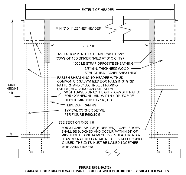
675 IAC 14-4.3-100 Section R602.10.5; continuous structural panel sheathing
Authority: Sec. 100. Make the following changes to Section 602.10.5: R602.10.5:
(a) (1) In the first sentence, delete "all walls and interior braced wall lines," and insert "an exterior wall line," and, after "braced wall panel lengths", insert "for such a wall line".
(b) (2) In the second sentence, after "R602.10.5", insert "for such a wall line".
(c) (3) Add an exception to read as follows: Exception: Vertical wall segments in the first of one or first of two story buildings next to garage openings shall be permitted to have 6:1 height-to-width ratio (with height being measured from top of header to sill plate) when constructed in accordance with the following provisions. Each panel shall have a length of not less than 16 inches (406 mm) and a height of not more than 10 feet (3,048 mm). Each panel shall be sheathed on one face with a single layer of 3/8 inch minimum thickness (9.5 mm) wood structural panel sheathing nailed with 8d common or galvanized box nails in accordance with Figure R602.10.5(2). The wood structural panel sheathing shall extend up over the solid swan sawn or glued-laminated header and shall be nailed in accordance with Figure R602.10.5(2). The header shall extend between the inside faces of the first full-length outer studs of each panel. The clear span of the header between the inner studs of each panel shall be not less than 6 feet (1,829 mm) and not more than 18 feet (5,486 mm) in length. A strap with an uplift capacity of not less than 1,000 pounds (454 kg) shall fasten the header to the side of the inner studs opposite the sheathing. Two anchor bolts shall be installed in accordance with Section 403.1.6, R403.1.6, and plate washers shall be
a minimum of 2 inches by 2 inches by 3/16 inch (51 mm by 51 mm by 4.8 mm) thick and shall be used on each bolt. This exception is only permitted in Seismic Design Categories A-C.
(d) (4) Add FIGURE R602.10.5(2) to read as follows:
(Fire Prevention and Building Safety Commission;
SECTION 33. 675 IAC 14-4.3-100.5 IS ADDED TO READ AS FOLLOWS:
675 IAC 14-4.3-100.5 Section R602.10.8; connections
Authority:
Sec. 100.5. In the second sentence of Section R602.10.8, after "sills", add "or soles.".
(Fire Prevention and Building Safety Commission;
SECTION 34. 675 IAC 14-4.3-108 IS AMENDED TO READ AS FOLLOWS:
675 IAC 14-4.3-108 Section R606.10; anchorage
Authority: Sec. 108. Add an exception to Delete Section R606.10 and substitute to read as follows: EXCEPTION: Above grade masonry foundation walls in Seismic Design Category C1 are exempt from the requirements of Figure R606.10(3) and shall comply with the requirements of SECTION R404. be anchored to floor, roof, and foundation systems in accordance with details of Figure R606.10(1). In seismic zone C1, above grade masonry walls shall be anchored to floor, roof, and foundation systems in accordance with details of Figure R606.10(1) and Figure R606.10(2). Below grade masonry foundation walls shall be designed and constructed to comply with Sections R403 and R404.
(Fire Prevention and Building Safety Commission;
SECTION 35. 675 IAC 14-4.3-109 IS AMENDED TO READ AS FOLLOWS:
675 IAC 14-4.3-109 Section R606.11; seismic requirements
Authority: Sec. 109. Make the following changes to SECTION R606.11: (a) Add, at the end of the first sentence, "C1" between "C" and "D1".
SECTION 36. 675 IAC 14-4.3-110 IS AMENDED TO READ AS FOLLOWS:
675 IAC 14-4.3-110 Section R606.11.2; seismic design category C
Authority: Sec. 110. Make the following changes to Section R606.11.2:
(a) (1) Change the title and text of Section R606.11.2 to read as follows: Seismic Design Category C and C1. Above grade masonry walls in structures located in seismic design category C and C1 shall comply with the requirements of this Section.
(b) Add an exception to read as follows: EXCEPTION: (2) Below grade masonry foundation walls in Seismic Design Category C and C 1 are exempt from the requirements of Figure R606.10(3) and shall be designed and constructed to comply with Section R404.
(Fire Prevention and Building Safety Commission;
SECTION 37. 675 IAC 14-4.3-115 IS AMENDED TO READ AS FOLLOWS:
675 IAC 14-4.3-115 Section R611.1; general
Authority: Sec. 115. Delete the last sentence of Section R611.1 and substitute to read as follows: In seismic design category C1, for a townhouse having one or more insulating concrete form (ICF) exterior walls, the noninsulating concrete form other exterior walls and interior load bearing walls shall comply with the applicable anchorage and seismic provisions of SECTION R611". this code.
(Fire Prevention and Building Safety Commission;
SECTION 38. 675 IAC 14-4.3-115.5 IS ADDED TO READ AS FOLLOWS:
675 IAC 14-4.3-115.5 Section R702.3.7; limitations
Authority:
Sec. 115.5. Add a title and the text of Section R702.3.7 to read as follows: R702.3.7 Limitations. Water-resistant gypsum backing board shall not be used where there will be direct exposure to water or in areas subject to continuous high humidity.
(Fire Prevention and Building Safety Commission;
SECTION 39. 675 IAC 14-4.3-115.6 IS ADDED TO READ AS FOLLOWS:
675 IAC 14-4.3-115.6 Section R702.4.4; cement, fiber-cement, and glass mat gypsum backers
Authority:
Sec. 115.6. Add a title and the text of Section R702.4.4 to read as follows: R702.4.4 Cement, fiber-cement, and glass mat gypsum backer. Cement, fiber-cement, and glass mat gypsum backers in compliance with ASTM C 1288, C 1325, or C 1178 and installed in accordance with manufacturers' recommendations shall be permitted as backers for wall tile in tub and shower areas and wall panels in shower areas.
(Fire Prevention and Building Safety Commission;
SECTION 40. 675 IAC 14-4.3-116 IS AMENDED TO READ AS FOLLOWS:
675 IAC 14-4.3-116 Table 703.4; weather-resistant siding attachment and minimum thickness
Authority: Sec. 116. Change TABLE R703.4 as follows:
(a) (1) Change footnote m to read as follows: For masonry veneer, a weather-resistant sheathing paper is not required over water-repellent sheathing materials applied according to manufacturer's instructions and a 3/4 inch (19 mm) air space is provided. When the 3/4 inch (19 mm) space is filled with mortar, a weather-resistant sheathing paper is required over the sheathing.
(b) (2) In the column titled "Sheathing paper required", add a footnote designation "s" "aa" at all three (3) places for Horizontal Aluminum and for Vinyl Siding.
(c) (3) Add a new footnote "s" "aa" to read as follows: Unless required by the siding manufacturer's installation instructions.
(Fire Prevention and Building Safety Commission;
SECTION 41. 675 IAC 14-4.3-125.5 IS ADDED TO READ AS FOLLOWS:
675 IAC 14-4.3-125.5 Section R802.10.3; bracing
Authority:
Sec. 125.5. Change the last sentence of Section R802.10.3 to read as follows: In the absence of specific bracing requirements, trusses shall be braced in accordance with standard industry lateral restraint and diagonal bracing details.
(Fire Prevention and Building Safety Commission;
SECTION 42. 675 IAC 14-4.3-126 IS AMENDED TO READ AS FOLLOWS:
675 IAC 14-4.3-126 Section R802.10.4; alterations to trusses
Authority: Sec. 126. Change the first sentence of Section R802.10.4 to read as follows: Truss members shall not be cut, notched, drilled, spliced, or otherwise altered in any way without the acceptance of an architect registered under IC 25-4 or a professional engineer registered under IC 25-31 , the manufacturer of the truss members, or approved approval by the building official.
(Fire Prevention and Building Safety Commission;
SECTION 43. 675 IAC 14-4.3-127 IS AMENDED TO READ AS FOLLOWS:
675 IAC 14-4.3-127 Section R802.10.5; truss to wall connection
Authority: Sec. 127. Change Add exceptions to Section R802.10.5 as follows: (a) Delete "approved connector" and substitute "mechanical fasteners or connectors".
1. In exposure category B, 24" o/c maximum mono-pitch trusses up to 10' in length that are not girders. Such trusses shall be fastened with three 0.131" diameter × 3" long toenails at each bearing. Truss length shall be the horizontal projection of the truss including all overhangs.
2. In exposure category B, 24" o/c maximum trusses that are not mono-pitch trusses up to 30' in length that are not girders. Such trusses shall be fastened with three 0.131" diameter × 3" long toenails at each bearing. Truss length shall be the horizontal projection of the truss including all overhangs.
SECTION 44. 675 IAC 14-4.3-132.5 IS ADDED TO READ AS FOLLOWS:
675 IAC 14-4.3-132.5 Section R905.2.8.1; base and cap flashing
Authority:
Sec. 132.5. Change Section R905.2.8.1 to read as follows: Base flashings (valley linings or base flashing at roof penetrations) and cap flashing (step, dormer, and counter flashing) shall be installed in accordance with manufacturer's installation instructions. Base flashing shall be of either corrosion-resistant metal of minimum nominal 0.019-inch thickness, mineral surface minimum 77 pounds (34.96 kg) per 100 square foot (3.76 kg/m2) roll roofing, or any material approved for base flashing. Cap flashing shall be corrosion-resistant metal of minimum nominal 0.019-inch thickness.
(Fire Prevention and Building Safety Commission;
SECTION 45. 675 IAC 14-4.3-132.6 IS ADDED TO READ AS FOLLOWS:
675 IAC 14-4.3-132.6 Section R905.2.8.2; valleys
Authority:
Sec. 132.6. (a) In Section R905.2.8.2, item 2, delete "ASTM D 249" and substitute "ASTM D 3909 or ASTM D 6380 Class M".
(b) In Section R905.2.8.2, item 3, delete "ASTM D 224 Type II or Type III" and substitute "ASTM D 6380 Class S Type III, Class M Type II, or ASTM D 3909".
(Fire Prevention and Building Safety Commission;
SECTION 46. 675 IAC 14-4.3-132.7 IS ADDED TO READ AS FOLLOWS:
675 IAC 14-4.3-132.7 Section R905.2.8.3; crickets and saddles
Authority:
Sec. 132.7. Change Section R905.2.8.3 to read as follows: A cricket or saddle shall be installed on the ridge side of any chimney more than 30 inches (762 mm) wide as measured perpendicular to the slope. Cricket or saddle coverings shall be sheet metal in accordance with Section R905.2.8.1 or of the same material as the roof covering. Base and cap flashing of the cricket or saddle shall also be in accordance with Section R905.2.8.1.
(Fire Prevention and Building Safety Commission;
SECTION 47. 675 IAC 14-4.3-139 IS AMENDED TO READ AS FOLLOWS:
675 IAC 14-4.3-139 Chapter 11; energy efficiency
Authority: Sec. 139. Delete the text of Chapter 11 in its entirety and substitute the following: Section N1101; GENERAL
N1102.2 Fenestration exemption. Up to 1 percent of the total glazing area shall be exempt from U-factor requirements.
(Fire Prevention and Building Safety Commission; N1101.1 Scope. This chapter sets forth energy-efficiency requirements for the design and construction of buildings regulated by this code.
Exception: Provided that they are separated by building envelope assemblies from the remainder of the building, portions of the building that do not enclose conditioned space shall be exempt from the building envelope provisions but shall comply with the provisions for building mechanical and service water systems.
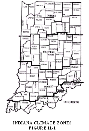
N1101.2 Compliance. Compliance with this chapter shall be demonstrated by meeting the requirements of the applicable sections and tables of Sections N1101, N1102, N1104, and N1105 of this chapter. Compliance with Section N1103 or N1106 is an alternative to compliance with Section N1102. Where applicable, provisions are based on the climate zone where the building is located as set forth in FIGURE 11-1 below.
N1101.2.1 Eligible buildings. Compliance for detached one and two family dwellings and for townhouses shall be demonstrated by meeting the requirements of subsection N1101.2.
N1101.3 Materials and equipment. Materials and equipment shall be identified as complying with the provisions of this chapter. Materials and equipment shall be listed and labeled for their intended use and shall be installed in accordance with the manufacturer's installation instructions.
N1101.3.1 Insulation. The thermal resistance (R-value) shall be indicated on all insulation and the insulation installed such that the R-value can be verified during inspection, or evidence of compliance of the installed R-value shall be provided at the job site by the insulation installer.
N1101.3.2 Fenestration. The U-factor of fenestration shall be determined in accordance with NFRC 100 by an accredited, independent laboratory and labeled and certified by the manufacturer. The solar heat gain coefficient (SHGC) of fenestration shall be determined in accordance with NFRC 200 by an accredited, independent laboratory and labeled and certified by the manufacturer.
N1101.3.2.1 Default fenestration performance. When a manufacturer has not determined a fenestration product's U-factor in accordance with NFRC 100, compliance shall be determined by assigning such products a default U-factor from TABLES 11-1 and 11-2. When a manufacturer has not determined a fenestration product's SHGC in accordance with NFRC 200, compliance shall be determined by assigning such products a default SHGC from TABLE 11-3.
| TABLE 11-1 |
| U-FACTOR DEFAULT TABLE FOR WINDOWS, GLAZED DOORS, AND SKYLIGHTS |
| FRAME MATERIAL AND PRODUCT TYPEa | SINGLE GLAZED | DOUBLE GLAZED | |
| Metal without thermal break | |||
| Operable (including sliding and swinging glass doors) | 1.27 | 0.87 | |
| Fixed | 1.13 | 0.69 | |
| Garden window | 2.60 | 1.81 | |
| Curtain wall | 1.22 | 0.79 | |
| Skylight | 1.98 | 1.31 | |
| Site-assembled sloped/overhead glazing | 1.36 | 0.82 | |
| Metal with thermal break | |||
| Operable (including sliding and swinging glass doors) | 1.08 | 0.65 | |
| Fixed | 1.07 | 0.63 | |
| Curtain wall | 1.11 | 0.68 | |
| Skylight | 1.89 | 1.11 | |
| Site-assembled sloped/overhead glazing | 1.25 | 0.70 | |
| Reinforced vinyl/metal clad wood | |||
| Operable (including sliding and swinging glass doors) | 0.90 | 0.57 | |
| Fixed | 0.98 | 0.56 | |
| Skylight | 1.75 | 1.05 | |
| Wood/vinyl/fiberglass | |||
| Operable (including sliding and swinging glass doors) | 0.89 | 0.55 | |
| Fixed | 0.98 | 0.56 | |
| Garden window | 2.31 | 1.61 | |
| Skylight | 1.47 | 0.84 | |
| TABLE 11-2 |
| U-FACTOR DEFAULT TABLE FOR NONGLAZED DOORS |
| DOOR TYPE Steel doors (1.75 inches thick) | WITH FOAM CORE 0.35 WITHOUT STORM DOOR | WITHOUT FOAM CORE 0.60 WITH STORM DOOR | |
| Wood doors (1.75 inches thick) | |||
| Panel with 0.438 inch panels | 0.54 | 0.36 | |
| Hollow core flush | 0.46 | 0.32 | |
| Panel with 1.125 inch panels | 0.39 | 0.28 | |
| Solid core flush | 0.40 | 0.26 | |
| For SI: 1 inch = 25.4 mm. |
| TABLE 11-3 |
| SHGC DEFAULT TABLE FOR FENESTRATION |
| PRODUCT DESCRIPTION | SINGLE GLAZED | DOUBLE GLAZED | |||||||
| Clear | Bronze | Green | Gray | Clear + Clear | Bronze + Clear | Green + Clear | Gray + Clear | ||
| Metal frames | |||||||||
| Operable | 0.75 | 0.64 | 0.62 | 0.61 | 0.66 | 0.55 | 0.53 | 0.52 | |
| Fixed | 0.78 | 0.67 | 0.65 | 0.64 | 0.68 | 0.57 | 0.55 | 0.54 | |
| Nonmetal frames | |||||||||
| Operable | 0.63 | 0.54 | 0.53 | 0.52 | 0.55 | 0.46 | 0.45 | 0.44 | |
| Fixed | 0.75 | 0.64 | 0.62 | 0.61 | 0.66 | 0.54 | 0.53 | 0.52 | |
N1101.3.2.2 Air leakage. The air leakage of prefabricated fenestration shall be determined by the manufacturer. Alternatively, the fenestration shall be installed in accordance with the maximum allowable rates in TABLE 11-4.
Exception: Site-constructed windows and doors sealed in accordance with Section N1102.1.10.
| TABLE 11-4 |
| ALLOWABLE AIR FILTRATION RATESa |
| WINDOWS (cfm per square foot of window area) | DOORS (cfm per square foot of door area) | |
| Sliders | Swinging | |
| 0.3b | 0.3 | 0.5 |
| For SI: 1 cfm/ft2 = 0.00508 m3/ (s × m2). |
| aWhen tested in accordance with NFRC 400. |
| bSee AAMA/WDMA 101/I.S. 2. |
N1101.3.3 Minimum Insulation R-Values. The minimum insulation R-values permitted using tradeoffs from Section N1103 or Section N1106 for all climate regions shall be R-13 for abovegrade walls, R-30 for ceilings, and R-19 for floors.
N1101.4 Alternate energy materials, methods, and design. The provisions of this code are not intended to prevent the use of any material, method of construction, design, or insulating system not specifically prescribed herein, provided that such construction, design, or insulating system has been approved as meeting the intent of the code.
Compliance with specific provisions and the intent of this code shall be determined through the use of approved computer software (such as REScheck or MECcheck provided by the Department of Energy), worksheets, compliance manuals (from ASTM, etc.), and other similar materials.
SECTION N1102. COMPLIANCE BY PRESCRIPTIVE SPECIFICATIONS ON INDIVIDUAL COMPONENTS
N1102.1 Thermal performance criteria. The minimum required insulation R-value or maximum required U-factor for each element in the building thermal envelope (fenestration, roof/ceiling, opaque wall, floor, slab edge, crawlspace wall, and basement wall) shall be in accordance with criteria in TABLE 11-5.
| TABLE 11-5 |
| INSULATION AND FENESTRATION REQUIREMENTS BY COMPONENTSa |
| 78% AFUE or 6.8 HSPF and 10 SEER |
| REGION See Figure 11-1 | GLAZING U-VALUE | SKYLIGHT U-VALUEb | CEILING R-VALUE | WALL R-VALUEce | FLOOR R-VALUEd | BASEMENT WALL R-VALUEe | SLAB PERIMETER R-VALUE/DEPTHf | CRAWLSPACE WALL R-VALUEe |
| North | .35 | 0.60 | 30 | 15 plus 1 | 25 | 13 / 7 ft. | 10 / 4 ft. | 7 / |
| Central | .45 | 0.60 | 30 | 13 plus 1 | 25 | 10 / 7 ft. | 10 / 4 ft. | 10 / |
| South | .45 | 0.60 | 30 | 13 plus 1 | 19 | 7 / 7 ft. | 7 / 3 ft. | 7 / |
| Ohio River | .45 | 0.60 | 30 | 13 | 19 | 7 / 4 ft. | 3.5 / 2 ft. | 3 / |
| aR-values are minimums. U-factors and SHGC are maximums. R-19 insulation shall be permitted to be compressed except as noted. The glazing U-factors are for windows only. The default U-factors for doors are in TABLES 11-1 and 11-2. The maximum door U-values to be allowed with this table are as follows: main exit, 0.54; other exit doors, 0.34; sliding glass doors, French doors, and atrium doors, 0.55. |
| bSkylights are glazed fenestration less than 60 degrees from horizontal. |
| cCavity insulation plus sheathing (wood frame walls only). Steel frame walls require the installation of an exterior insulated sheathing in accordance with Section |
| dOr insulation sufficient to fill the cavity, R-19 minimum. |
| eBox or rim joist cavity spaces must be insulated |
| fThe insulation shall be installed from the top of the slab to the required depth, horizontally or vertically, or a combination of both, until the required depth is achieved. |
N1102.1.1 Exterior walls. The minimum required R-value in TABLES 11-5 shall be met by the sum of the R-values of the insulation materials installed in framing cavities and/or sheathing applied and not by framing, dry wall, or exterior siding materials. Insulation separated from the conditioned space by a vented space shall not be counted towards the required R-value.
N1102.1.1.1 Mass walls. For purposes of this section, the following definitions apply: Mass walls with exterior insulation position are those that have the entire effective mass layer interior to an insulation layer. Mass walls with integral insulation position are those that have either insulation and mass materials well mixed as in wood (logs) or substantially equal amounts of mass material on the interior and exterior of insulation as in concrete masonry units with insulated cores or masonry cavity walls. Mass walls with interior insulation position are those that have the mass material located exterior to the insulating material.
Mass walls shall be permitted to meet the mass wall criteria in TABLE 11-6 based on the insulation position and the climate zone where the building is located. Other mass walls shall meet the frame wall criteria for the building type and the climate zone where the building is located based on the sum of interior and exterior insulation.
Mass walls not meeting either of the above descriptions for exterior or integral positions shall meet the requirements for other mass walls in TABLE 11-6. The R-value for a solid concrete wall with a thickness of 4 inches (102 mm) or greater is R-1.1. R-values for other assemblies are permitted to be based on hot box tests.
| TABLE 11-6 |
| MASS WALL PRESCRIPTIVE BUILDING ENVELOPE REQUIREMENTS |
| Building Location | Mass Wall Assembly R-Value (hr ft2°F)/Btu | ||
| Zone | HDD | Exterior or Integral Insulation | Other Mass Walls |
| Northern | 6,300 | R-13 | R-15.2 |
| Central | 5,700 | R-13 | R-15.2 |
| South | 5,000 | R-8 | R-15.2 |
| Ohio River | 4,300 | R-8 | R-15.2 |
| For SI: 1(hr ft2°F)/Btu = 0.176 m2 K/W |
N1102.1.1.2. Steel-frame walls. When steel framing construction is used, insulated sheathing with an R-5 value shall be installed in addition to the minimum required R-value for frame walls determined in accordance with TABLE 11-5.
N1102.1.2 Ceilings. The required "Ceiling R-value" in TABLE 11-5 assumes standard truss or rafter construction and shall apply to all roof/ceiling portions of the building thermal envelope including cathedral ceilings. R-30 shall be permitted to be compressed over the top plate to obtain the required rafter air spaces. R-30 shall be permitted to be used over the top plate where R-38 is required. R-38 shall be permitted over the top plate where R-49 is required.
N1102.1.3 Opaque doors. Opaque doors separating conditioned and unconditioned space shall have a maximum U-factor of 0.35. One opaque door shall be permitted to be exempt from this U-factor requirement.
N1102.1.4 Floors. The required R-value in TABLE 11-5 shall apply to all floors, except any individual floor assembly with over 25 percent of its conditioned floor area exposed directly to outside air shall meet the R-value requirement in TABLE 11-5 for ceilings.
N1102.1.5 Basement walls. When insulating basement walls, the required R-values shall be applied from the top of the basement wall to the depth required by TABLE 11-5.
N1102.1.6 Slab-on-grade floors. For slabs with a top edge 8 inches (203 mm) or less above or 12 inches (305 mm) or less below finished grade, the required R-value in TABLE 11-5 shall be applied to the outside of the foundation or the inside of the foundation wall. The insulation shall extend downward from the top of the slab, or downward to the bottom of the slab and then horizontally in either direction, for the minimum distance listed in TABLE 11-5.
When installed between the exterior wall and the edge of the interior slab, the top edge of the insulation shall be permitted to be cut at a 45 degree (0.79 radians) angle away from the exterior wall. Insulation extending horizontally away from the building shall be protected as set forth by Section R403.3.1.
R-2 shall be added to the values in TABLE 11-5 where uninsulated hot water pipes, air distribution ducts, or electric heating cables are installed within or under the slab.
N1102.1.7 Crawlspace walls. Where the floor above the crawlspace is uninsulated, and the crawlspace is not vented to outside air, insulation shall be installed on crawlspace walls as required in TABLE 11-5. The Crawlspace wall insulation shall be applied inside of the crawlspace wall, downward from the sill plate to the distance required by TABLE 11-5. permanently fastened to the wall and extend downward from the floor to the finished grade level and then vertically and/or horizontally for at least an additional 24 inches (610 mm). The exposed earth in all crawlspace foundations shall be covered with a continuous 6 mil vapor retarder having a maximum permeance rating of 1.0 perm (5.74525 × 10⁻¹¹ kg/(Pa × s × m2)).
N1102.1.8 Masonry veneer. For exterior foundation insulation, that horizontal portion of the foundation that supports a masonry veneer shall not be required to be insulated.
N1102.1.9 Protection. Exposed Insulating materials applied to the exterior of foundation walls shall be protected from damage or deterioration. The protection shall extend at least by a rigid, opaque, and weather-resistant covering extending 6 inches (152 mm) below finished grade. level.
N1102.1.10 Air leakage. Exterior joints, seams, or penetrations in the building envelope, separating conditioned and unconditioned spaces, that are sources of air leakage shall be sealed with caulking materials, closed with gasketing systems, taped, or covered with moisture vapor-permeable house-wrap. Sealing materials spanning joints between dissimilar construction materials shall allow for differential expansion and contraction of the construction materials. This includes sealing around tubs and showers, at the attic and crawlspace panels, at recessed lights, and around all plumbing and electrical penetrations. These are openings located in the building envelope between conditioned space and unconditioned space or between the conditioned space and the outside.
EXCEPTION: Exceptions:
1. Vertical seams and joints with gaps of 1/8 inch (3 mm) or less that break over a stud.
2. Unvented crawlspaces.
N1102.1.11 Recessed lighting fixtures. luminaires. When installed in the building envelope, recessed lighting fixtures luminaires shall meet one of the following:
1. Type IC rated, manufactured with no penetrations between the inside of the recessed fixture luminaire and ceiling cavity and sealed or gasketed to prevent air leakage into the unconditioned space.
2. Type IC or non-IC rated, installed inside a sealed box constructed from a minimum 0.5 inch (12.7 mm) thick gypsum wallboard or constructed from a preformed polymeric vapor barrier, or other airtight assembly manufactured for this purpose, while maintaining required clearances of not less than 0.5 inch (12.7 mm) from combustible material and not less than 3 inches (76 mm) from insulation material.
3. Type IC rated admitting no more than 2.0 cubic feet per minute (cfm) (0.944L/s) of air movement from the conditioned space to the ceiling cavity. The lighting fixture luminaire shall be tested at 1.57 psi (75 Pa) pressure difference and shall be labeled.
SECTION N1103 COMPLIANCE BY TOTAL BUILDING ENVELOPE PERFORMANCE
N1103.1 Compliance with this section is an alternative to compliance with Section N1102.
N1103.2 Compliance by total building envelope performance. The building envelope design of a proposed building shall be permitted to deviate from the Uo-factors, U-factors, or R-values specified in TABLE 11-7, provided the total thermal transmission heat gain or loss for the proposed building envelope does not exceed the total heat gain or loss resulting from the proposed building's conformance to the values specified in TABLE 11-7. For basement and crawlspace walls that are part of the building envelope, the U-factor of the proposed foundation shall be adjusted by the R-value of the adjacent soil where the corresponding U-factor in TABLE 11-7 is similarly adjusted. Heat gain or loss calculations for slab edge and basement or crawlspace wall foundations shall be determined using approved methods.
| TABLE 11-7 a, b, c |
| EQUIVALENT U-FACTORS |
| REGION | GLAZING | SKYLIGHT | CEILING | WALL | MASS WALL | FLOOR | BASEMENT | SLAB PERIMETER | CRAWLSPACE |
| North | 0.35 | 0.60 | 0.035 | 0.064 | 0.077 | 0.037 | 0.055 | 0.684 | 0.076 |
| Central | 0.45 | 0.60 | 0.035 | 0.074 | 0.077 | 0.042 | 0.064 | 0.684 | 0.100 |
| South | 0.45 | 0.60 | 0.035 | 0.074 | 0.125 | 0.045 | 0.078 | 0.727 | 0.109 |
| Ohio River | 0.45 | 0.60 | 0.035 | 0.077 | 0.125 | 0.047 | 0.093 | 0.825 | 0.196 |
| aNonfenestration U-factors shall be obtained from this table, measurement, calculation, or an approved source. |
| bFor 78 percent AFUE furnaces or 6.8 HSPF and 10 SEER except where otherwise noted. |
| cThe maximum door U-values to be allowed with this table are as follows: main exit, 0.54; other exit doors, 0.34; sliding glass doors, French doors, and atrium doors, 0.55. |
SECTION N1104 MECHANICAL SYSTEMS
N1104.1 Heating and air conditioning appliance and equipment performance. Performance of equipment listed in TABLE 11-8 is covered by preemptive federal law. Appliances and equipment not listed in TABLE 11-8 shall be approved. Data furnished by the equipment supplier, or certified under a nationally recognized certification procedure, shall be used to satisfy these requirements. All such equipment shall be installed in accordance with the manufacturer's instructions.
| TABLE 11-8 |
| MINIMUM EQUIPMENT PERFORMANCE |
| EQUIPMENT CATEGORY | SUBCATEGORYe | REFERENCED STANDARD | MINIMUM PERFORMANCE |
| Air-cooled heat pumps heating mode < 65,000 Btu/h cooling capacity | Split systems | 6.8 HSPFa, b | |
| ARI 210/240 | |||
| Single package | 6.6 HSPFa, b | ||
| Gas-fired or oil-fired furnace < 225,000 Btu/h | DOE 10 CFR Part 430, Subpart B, APPENDIX N | AFUE 78%b, Et 80% c | |
| Gas-fired or oil-fired steam and hot water boilers < 300,000 Btu/h | DOE 10 CFR Part 430, Subpart B, APPENDIX N | AFUE 78%b, d | |
| Air-cooled air conditioners and heat pumps cooling mode < 65,000 Btu/h cooling capacity | Split systems | 10.0 SEERb | |
| ARI 210/240 | |||
| Single package | 9.7 SEERb |
| For SI: 1 Btu/h = 0.2931 W. |
| aFor multicapacity equipment, the minimum performance shall apply to each capacity step provided. Multicapacity refers to manufacturer-published ratings for more than one capacity mode allowed by the product's controls. |
| bThis is used to be consistent with the National Appliance Energy Conservation Act (NAECA) of 1987 (Public Law 100-12). |
| cThese requirements apply to combination units not covered by NAECA (three-phase power or cooling capacity 65,000 Btu/h). |
| dExcept for gas-fired steam boilers, for which the minimum AFUE shall be 75 percent. |
| eSeasonal rating. |
N1104.2 Controls. At least one thermostat shall be provided for each separate heating, cooling, or combination heating and cooling system. Heat pumps shall have controls that prevent supplementary electric resistance heater operation when the heating load can be met by the heat pump alone. Supplementary heater operation shall be permitted during outdoor coil defrost cycles not exceeding 15 minutes.
N1104.3 Duct insulation. All portions of the air distribution system that serve the permanent heating, ventilating, and air conditioning systems shall be installed in accordance with Section M1601 and be insulated to an installed R-4.2 when system components are located within the building but outside of conditioned space and R-8 when located outside of the building. When located within a building envelope assembly, at least R-8 shall be applied between the duct and that portion of the assembly furthest from conditioned space.
Exception: Exhaust air ducts and portions of the air distribution system within appliances or equipment.
N1104.4 Duct sealing. All ducts shall be sealed in accordance with Section M1601.3.1.
N1104.5 Piping insulation. All mechanical system piping that serves the permanent heating, ventilating, and air conditioning systems shall be insulated in accordance with TABLE 11-9.
Exception: Piping installed within appliances and equipment or piping serving fluids between 55°F (13°C) and 120°F (49°C).
| TABLE 11-9 |
| MINIMUM HVAC PIPING INSULATION THICKNESSESa |
| FLUID TEMPERATURE RANGE (°F) | INSULATION THICKNESS (inches)b | |
| HEATING SYSTEMS | ||
| Low pressure/temperature | 201–250 | 1.5 |
| Low temperature | 120–200 | 1.0 |
| Steam condensate (for feed water) | Any | 1.5 |
| COOLING SYSTEMS | ||
| Chilled water, refrigerant, or brine | 40–55 | 0.75 |
| Below 40 | 1.25 |
| For SI: 1 inch = 25.4 mm, °C = (°F - 32)/1.8. | |||
| aThe pipe insulation thicknesses specified in this table are based on insulation R-values ranging from R-4 to R-4.6 per inch of thickness. For materials with an R-value greater than R-4.6, the insulation thickness specified in this table may be reduced as follows: | |||
| New Minimum Thickness | = | 4.6 × Table Thickness | |
| Actual R-value | |||
| For materials with an R-value less than R-4, the minimum insulation thickness shall be increased as follows: | |||
| New Minimum Thickness | = | 4.0 × Table Thickness | |
| Actual R-value | |||
| bFor piping exposed to outdoor air, increase thickness by 0.5 inch. | |||
SECTION N1105 SERVICE WATER HEATING
N1105.1 Water heating appliance and equipment performance. Performance of equipment listed in TABLE 11-10 is covered by preemptive federal law. Appliances and equipment not listed in TABLE 11-10 shall be approved.
| TABLE 11-10 |
| REQUIRED PERFORMANCE OF DOMESTIC HOT WATER HEATING EQUIPMENT SUBJECT TO MINIMUM FEDERAL STANDARDS |
| CATEGORY | MAXIMUM INPUT RATING | MINIMUM EFFICIENCY |
| Electric; storage or instantaneous | 12 kW | 0.93 - 0.00132 × Va |
| Gas; storage | 75,000 Btu/h | 0.62 - 0.0019 × Va |
| Gas; instantaneous | 200,000 Btu/h | 0.62 - 0.0019 × Va |
| Oil; storage | 105,000 Btu/h | 0.59 - 0.0019 × Va |
| Oil; instantaneous | 210,000 Btu/h | 0.59 - 0.0019 × Va |
| For SI: 1Btu/h = 0.2931 W, 1 gallon = 3.785 L. |
| aV is the rated storage volume in gallons as specified by the manufacturer. |
N1106 ALTERNATE DESIGN
N1106.1 Chapter 4, Residential Building Design by Systems Analysis and Design of Buildings Utilizing Renewable Energy Sources, of the International Energy Conservation Code 2000, except as amended in subsection N1106.2, is an alternative to compliance with Sections N1102 and N1103.
N1106.2 (a) Change subsection 402.1 to read as follows: Compliance with this chapter will require an analysis of the annual energy usage, completed during the building design phase, and hereinafter called the "annual energy analysis".
(b) Delete the exception from subsection 402.1 without substitution.
(c) Delete "Chapter 5" from subsection 402.1.1 and substitute "TABLE 11-5, TABLE 11-7, or TABLE 11-11". Delete all exceptions in subsection 402.1.1.
(d) Delete TABLES 402.1.1(1) and 402.1.1(2) including their footnotes.
(e) In subsection 402.1.3.1.4, delete "Table 102.5.2(3)" and substitute "TABLE 11-3".
(f) In subsection 402.1.3.6, delete "Type A-1 Residential building" and substitute "1 or 2 family dwelling" and delete "Type A-2 Residential building" and substitute "townhouse".
(g) Add the following to the last sentence of subsection 402.1.3.10: "See subsection R303.1 for ventilation requirements for one and two family dwellings or townhouses.".
(h) In subsection 402.1.3.11, delete "Table 502.2" and substitute "TABLE 11-5".
(i) In subsection 402.4.1, delete "as required in Chapter 3" and substitute "as follows:" and the following table:
| TABLE 11-11 |
| THERMAL DESIGN PARAMETERS EXTERNAL DESIGN CONDITIONS |
| Northern | Central | South | Ohio River | |
| WINTER Design Dry-Bulb °F | 1° | 2° | 9° | 9° |
| SUMMER Design Wet-Bulb °F | 73° | 74° | 75° | 75° |
| SUMMER Design Dry-Bulb °F | 89° | 90° | 93° | 93° |
| DEGREE DAYS HEATING | 6,300 | 5,700 | 5,000 | 4,300 |
(j) In subsection 402.5, delete "Chapter 4" and substitute "this chapter".
(k) In subsection 403.1.1.1, delete "Section 502.1.4.1" and substitute "TABLE 11-4".
SECTION 48. 675 IAC 14-4.3-143.5 IS ADDED TO READ AS FOLLOWS:
675 IAC 14-4.3-143.5 Section M1305.1.3; appliances in attics
Authority:
Sec. 143.5. Change Section M1305.1.3 to read as follows:
(Fire Prevention and Building Safety Commission;
(1) In Section M1305.1.3, add a second exception to read as follows: 2. Where the passageway is unobstructed and not less than 6 feet (1,829 mm) high and 22 inches (559 mm) wide for its entire length, the passageway shall not be more than 50 feet (15.25 m) long.
(2) Change Section M1305.1.3.1 to read as follows: A luminaire controlled by a switch located at the required passageway opening and a receptacle outlet shall be provided at or near the appliance location in accordance with Chapter 38.
(3) In Section M1305.1.4, add a second exception to read as follows: 2. Where the passageway is unobstructed and not less than 6 feet (1,829 mm) high and 22 inches (559 mm) wide for its entire length, the passageway shall not be limited in length.
(4) Change Section M1305.1.4.3 to read as follows: A luminaire controlled by a switch located at the required passageway opening and a receptacle outlet shall be provided at or near the appliance location in accordance with Chapter 38.
SECTION 49. 675 IAC 14-4.3-144 IS AMENDED TO READ AS FOLLOWS:
675 IAC 14-4.3-144 Section M1307.3.1; protection from impact
Authority: Sec. 144. Delete Change the title and text of Section M1307.3.1 to read as follows: M1307.3.1 Isolation from corrugated stainless steel tubing. Except where connected to gas supply piping, appliances shall be isolated from corrugated stainless steel tubing by a space separation of at least 2 inches (51 mm). See also Section G2411.1.
(Fire Prevention and Building Safety Commission;
SECTION 50. 675 IAC 14-4.3-144.5 IS ADDED TO READ AS FOLLOWS:
675 IAC 14-4.3-144.5 Section M1308.3; foundations and supports
Authority:
Sec. 144.5. Add a title and the text of Section M1308.3 to read as follows: M1308.3 Foundations and supports. Foundations and supports for outdoor mechanical systems shall be raised at least 1 1/2 inches (38.25 mm) above the finished grade and shall also conform to manufacturer's installation instructions.
(Fire Prevention and Building Safety Commission;
SECTION 51. 675 IAC 14-4.3-144.6 IS ADDED TO READ AS FOLLOWS:
675 IAC 14-4.3-144.6 Section M1406.2; clearances
Authority:
Sec. 144.6. Change Section M1406.2 to read as follows: Clearances for radiant heating panels or elements to any wiring, outlet boxes, and junction boxes used for installing electrical devices or mounting luminaires shall comply with Chapters 33 through 42 of this code.
(Fire Prevention and Building Safety Commission;
SECTION 52. 675 IAC 14-4.3-144.7 IS ADDED TO READ AS FOLLOWS:
675 IAC 14-4.3-144.7 Section M1410.1; general
Authority:
Sec. 144.7. Change Section M1410.1 to read as follows: Vented room heaters shall be tested in accordance with ASTM E 1509, UL 1482, or UL 896 and installed in accordance with their listing, the manufacturer's installation instructions, and the requirements of this code.
(Fire Prevention and Building Safety Commission;
SECTION 53. 675 IAC 14-4.3-145 IS AMENDED TO READ AS FOLLOWS:
675 IAC 14-4.3-145 Section M1411.3.1; auxiliary and secondary drain systems
Authority: Sec. 145. (a) In the first sentence of Section M1411.3.1, delete "damage to any building components will occur as a result of overflow from the equipment drain pan or stoppage in the condensate drain piping" and insert "installed over a finished ceiling".
(b) Add a sentence immediately after the next to last sentence of Section M1411.3.1 to read as follows: Such piping shall maintain a minimum horizontal slope in the direction of discharge of not less than 1/8 unit vertical in 12 units horizontal (1-percent slope).
(c) In the second sentence of Section M1411.3.1, item 3, add the phrase "conforming to UL 508" after "water level detection device."
(d) Add item 4 to Section M1411.3.1 to read as follows: 4. A water detection device conforming to UL 508 shall be provided that will shut off the equipment served in the event that the primary drain is blocked. The device shall be installed in the primary drain line, the overflow drain line or the equipment-supplied drain pan and shall be located at a point higher than the primary drain line connection and below the overflow rim of such pan.
SECTION 54. 675 IAC 14-4.3-145.5 IS ADDED TO READ AS FOLLOWS:
675 IAC 14-4.3-145.5 Section M1411.4; insulation of refrigerant piping
Authority:
Sec. 145.5. Change Section M1411.4 as follows:
(Fire Prevention and Building Safety Commission;
(1) Change the number of Section M1411.4 to read as follows: Section M1411.5 insulation of refrigerant piping.
(2) Add Section M1411.4 to read as follows: M1411.4 auxiliary drain pan. Category IV condensing appliances shall have an auxiliary drain pan when installed over a finished ceiling. These pans shall be installed in accordance with the applicable provisions of Section M1411.3.
Exception: Fuel-fired appliances that automatically shut down operation in the event of a stoppage in the condensate drainage system.
SECTION 55. 675 IAC 14-4.3-146.3 IS ADDED TO READ AS FOLLOWS:
675 IAC 14-4.3-146.3 Section M1601.3.6; duct separation
Authority:
Sec. 146.3. Add two (2) sentences to the end of Section M1601.3.6 to read as follows: Metal ducts and ducts containing metal shall be isolated from corrugated stainless steel tubing by a space separation of at least 2 inches (51 mm). See also Section G2411.1.
(Fire Prevention and Building Safety Commission;
SECTION 56. 675 IAC 14-4.3-146.5 IS ADDED TO READ AS FOLLOWS:
675 IAC 14-4.3-146.5 Section M1703.2.1; size of openings
Authority:
Sec. 146.5. Change the first sentence of M1703.2.1 to read as follows: Where directly communicating with the outdoors, or where communicating with the outdoors by means of vertical ducts, each opening shall have a free area of at least 1 square inch per 4,000 Btu/h of total input rating of all appliances in the space.
(Fire Prevention and Building Safety Commission;
SECTION 57. 675 IAC 14-4.3-148 IS AMENDED TO READ AS FOLLOWS:
675 IAC 14-4.3-148 Section M2005.5; anchorage of water heaters
Authority: Sec. 148. Add Section M2005.5 to the end of Section M2005 to read as follows: M2005.5 Anchorage of Water Heaters in Seismic Design Category C1. In seismic design category C1, all gas water heaters shall be anchored or fastened to resist horizontal displacement due to earthquake motion as provided in Section M1307.2.
EXCEPTION: Where approved excessive flow valves are implemented for the entire dwelling unit or for each gas appliance.
(Fire Prevention and Building Safety Commission;
SECTION 58. 675 IAC 14-4.3-148.5 IS ADDED TO READ AS FOLLOWS:
675 IAC 14-4.3-148.5 Section M2101.5; contact with building material
Authority:
Sec. 148.5. Add two (2) sentences to the end of Section M2101.5 to read as follows: Metal hydronic piping shall be isolated from corrugated stainless steel tubing by a space separation of at least 2 inches (51 mm). See also Section G2411.1.
(Fire Prevention and Building Safety Commission;
SECTION 59. 675 IAC 14-4.3-151 IS AMENDED TO READ AS FOLLOWS:
675 IAC 14-4.3-151 Section G2401.1; application
Authority: Sec. 151. (a) Delete the exception after the first paragraph of G2401.1 without substitution.
(b) Delete, in the second sentence of the second paragraph of Section G2401.1, ", inspection, operation, and maintenance" and add "and" before "testing" and delete the comma after "installation".
(Fire Prevention and Building Safety Commission;
SECTION 60. 675 IAC 14-4.3-153.5 IS ADDED TO READ AS FOLLOWS:
675 IAC 14-4.3-153.5 Section G2404.10; auxiliary and secondary drain systems
Authority:
Sec. 153.5. Add Section G2404.10 to read as follows: G2404.10 Auxiliary and secondary drain systems. Category IV condensing appliances shall be provided with an auxiliary drain pan when installed over a finished ceiling. Such pans shall be installed in accordance with the applicable provisions of Section M1411.
(Fire Prevention and Building Safety Commission;
Exception: An auxiliary drain pan shall not be required for appliances that automatically shut down operation in the event of a stoppage in the condensate drainage system.
SECTION 61. 675 IAC 14-4.3-154.5 IS ADDED TO READ AS FOLLOWS:
675 IAC 14-4.3-154.5 Section G2405.3; engineered wood products
Authority:
Sec. 154.5. Add Section G2405.3 to read as follows: G2405.3 Engineered wood products. Cuts, notches, and holes bored in trusses, structural composite lumber, structural glued-laminated members, and I-joists are prohibited except where permitted by manufacturer's recommendations or except where the effects of such alterations are specifically considered in the design of the member by a registered design professional.
(Fire Prevention and Building Safety Commission;
SECTION 62. 675 IAC 14-4.3-155.5 IS AMENDED TO READ AS FOLLOWS:
675 IAC 14-4.3-155.5 Section G2411.1; gas pipe bonding
Authority: Sec. 155.5. Delete the text of Section G2411.1 and add text to read as follows: All metal gas piping upstream from the equipment shutoff valve(s) shall be electrically continuous and shall be bonded to an effective ground-fault current path in accordance with Section E3509.7. Except where connected to appliances and at bonding connections, flexible metal gas corrugated stainless steel piping shall be isolated from metal gas piping, metal water piping, metal air ducts, metal structural framing, and all electrical wiring methods by a space separation of at least 2 inches. Table E3503.1, or the piping system listing requirements, shall be used to size the bonding conductor used to bond corrugated stainless steel gas tubing (CSST) to the electrical system.
(Fire Prevention and Building Safety Commission;
SECTION 63. 675 IAC 14-4.3-168.5 IS ADDED TO READ AS FOLLOWS:
675 IAC 14-4.3-168.5 Section G2422.1; connecting appliances
Authority:
Sec. 168.5. Add item 5 to Section G2422.1 to read as follows: 5. Corrugated stainless steel tubing (CSST) where installed in accordance with the manufacturer's instructions. Where CSST enters into an appliance, it shall be protected from damage by a semi-rigid sleeve or conduit.
(Fire Prevention and Building Safety Commission;
SECTION 64. 675 IAC 14-4.3-178 IS AMENDED TO READ AS FOLLOWS:
675 IAC 14-4.3-178 Section G2448.1; general
Authority: Sec. 178. (a) Add an exception to the end of Section G2448.1 to read as follows: Exception: Water heaters regulated by the Boiler and Pressure Vessel Rules Board (680 IAC 2 ) under IC 22-13-2-9 are not regulated by this code.
(b) Add Section G2448.1.2 to read as follows: G2448.1.2 Anchorage of water heaters in seismic design category C1. In seismic design category C1, water heaters shall be anchored or fastened to resist horizontal displacement due to earthquake motion as provided in Section M1307.2.
(Fire Prevention and Building Safety Commission;
SECTION 65. 675 IAC 14-4.3-191.5 IS ADDED TO READ AS FOLLOWS:
675 IAC 14-4.3-191.5 Section P2605.1; general
Authority:
Sec. 191.5. In Section P2605.1, add item 5 to read as follows: 5. Metal piping shall be isolated from corrugated stainless steel tubing by a space separation of at least 2 inches (51 mm). See also Section G2411.1.
(Fire Prevention and Building Safety Commission;
SECTION 66. 675 IAC 14-4.3-206 IS AMENDED TO READ AS FOLLOWS:
675 IAC 14-4.3-206 Section P3105.1; maximum distance of fixture trap to vent
Authority: Sec. 206. Add a note to TABLE P3105.1 to read as follows: NOTE: A trap arm serving only a bath tub, tub/shower combination, or shower may be increased to 9 feet with a slope of not less than 1/8 inch per foot.
(Fire Prevention and Building Safety Commission;
SECTION 67. 675 IAC 14-4.3-215 IS AMENDED TO READ AS FOLLOWS:
675 IAC 14-4.3-215 Section E3401; general
Authority: Sec. 215. Change Section E3401 as follows:
(a) (1) Delete the definition of APPROVED and substitute to read as follows: See the definition of APPROVED in Section R202.
(b) (2) Delete the definition of BRANCH CIRCUIT, GENERAL PURPOSE and substitute: A branch circuit that supplies two or more receptacles or outlets for lighting and appliances.
(c) (3) Change the definition of Grounding Conductor, Equipment to read as follows: The conductor used to connect the noncurrent-carrying metal parts of equipment, raceways, and other enclosures to the system grounded conductor or the grounding electrode conductor, or both, at the service equipment or at the source of a separately derived system.
(d) (4) Change the definition of Grounding Electrode Conductor to read as follows: The conductor used to connect the grounding electrode(s) to the equipment grounded grounding conductor or to the grounded conductor, or to both, at the service equipment, at each building or structure where supplied from by a common service, feeder(s) or branch circuit(s), or at the source of a separately derived system.
(e) (5) Delete the definition of LABELED and substitute as follows: See the definition of LABELED in Section R202.
(f) (6) Delete the definition of LISTED and substitute to read as follows: See the definition of LISTED AND LISTING in Section R202.
(Fire Prevention and Building Safety Commission;
SECTION 68. 675 IAC 14-4.3-220.1 IS ADDED TO READ AS FOLLOWS:
675 IAC 14-4.3-220.1 Section E3507.3; two or more buildings or structures supplied from a common service
Authority:
Sec. 220.1. Delete the title and first sentence of Section E3507.3 and substitute to read as follows: E3507.3 Buildings supplied by feeder(s) or branch circuit(s). Buildings or structures supplied by feeders(s) or branch circuit(s) shall have a grounding electrode or grounding electrode system installed in accordance with Section E3508. The grounding electrode conductor(s) shall be connected in a manner specified in Section E3507.1 or E3507.2.
(Fire Prevention and Building Safety Commission;
SECTION 69. 675 IAC 14-4.3-220.2 IS ADDED TO READ AS FOLLOWS:
675 IAC 14-4.3-220.2 Section E3507.3.1; equipment grounding conductor
Authority:
Sec. 220.2. After the second sentence of Section E3507.3.1, add a sentence to read as follows: The equipment grounding conductor shall be sized in accordance with Section R3808.12.
(Fire Prevention and Building Safety Commission;
SECTION 70. 675 IAC 14-4.3-227.1 IS AMENDED TO READ AS FOLLOWS:
675 IAC 14-4.3-227.1 Table E3701.4; allowable applications for wiring methods
Authority: Sec. 227.1. In the third column, in the sixteenth line of TABLE E3701.4, the sixteenth line, labeled "Run exposed and subject to physical damage", of the third column, labeled "EMT", delete "--" and insert "A".
(Fire Prevention and Building Safety Commission;
SECTION 71. 675 IAC 14-4.3-227.3 IS ADDED TO READ AS FOLLOWS:
675 IAC 14-4.3-227.3 Section E3701.5; isolation from gas piping
Authority:
Sec. 227.3. Add a title and the text to Section E3701.5 to read as follows: E3701.5 Isolation from corrugated stainless steel tubing. All wiring methods shall be isolated from corrugated stainless steel tubing by a space separation of at least 2 inches (51 mm). See also Section G2411.1.
(Fire Prevention and Building Safety Commission;
SECTION 72. 675 IAC 14-4.3-233 IS AMENDED TO READ AS FOLLOWS:
675 IAC 14-4.3-233 Section E3801.11; HVAC outlet
Authority: Sec. 233. In Change the last sentence of Section E3801.11 delete to read as follows: The receptacle outlet shall not be connected to the load side of the HVAC equipment disconnecting means, and crawlspace receptacles shall be protected in accordance with Section E3802.4. without substitution.
(Fire Prevention and Building Safety Commission;
SECTION 73. 675 IAC 14-4.3-233.3 IS ADDED TO READ AS FOLLOWS:
675 IAC 14-4.3-233.3 Section E3802.4; crawlspace receptacles
Authority:
Sec. 233.3. Add an exception to Section E3802.4 to read as follows: Single receptacles that serve sump pumps.
(Fire Prevention and Building Safety Commission;
SECTION 74. 675 IAC 14-4.3-234 IS AMENDED TO READ AS FOLLOWS:
675 IAC 14-4.3-234 Section E3802.8; boathouse receptacles
Authority: Sec. 234. Change Section 3802.8 to read as follows: All 125-volt, single phase, 15- or 20-ampere receptacles and outlets that supply boat hoists installed in and boathouses shall have ground-fault circuit-interrupter protection for personnel.
(Fire Prevention and Building Safety Commission;
SECTION 75. 675 IAC 14-4.3-242 IS AMENDED TO READ AS FOLLOWS:
675 IAC 14-4.3-242 Section E3807.7; cables
Authority: Sec. 242. (a) At the end of Part item 6, in the exception, delete ", the applicable article".
(b) After Part item 6 of the exception, add Part item 7 and Table E3807.8 to read as follows: Where installed as conduit or tubing, the allowable cable fill does not exceed that permitted for complete conduit or tubing systems by SECTION E3804.6. The allowable cable fill shall not exceed that permitted by Table E3807.8. A multiconductor cable having two or more conductors shall be treated as a single conductor for calculating the percentage of conduit fill area. For cables that have elliptical cross sections, the cross-sectional area calculation shall be based on the major diameter of the ellipse as a circle diameter.
(Fire Prevention and Building Safety Commission; | TABLE E3807.8 | |
| PERCENT OF CROSS SECTION OF CONDUIT AND TUBING FOR CONDUCTORS | |
| NUMBER OF CONDUCTORS | MAXIMUM PERCENT OF CONDUIT AND TUBING AREA FILLED BY CONDUCTORS |
| 1 | 53 |
| 2 | 31 |
| Over 2 | 40 |
SECTION 76. 675 IAC 14-4.3-243 IS AMENDED TO READ AS FOLLOWS:
675 IAC 14-4.3-243 Section E3808.7; load side equipment
Authority: Sec. 243. Add Exception 2 to Section E3808.7 to read as follows: Exception 2. It shall be permissible to ground meter enclosures by connection to the grounded circuit conductor on the load-side of the service if:
(Fire Prevention and Building Safety Commission; (1) all meter enclosures are located near immediately adjacent to the service disconnecting means; and
(2) the size of the grounded circuit conductor is not smaller than the size specified in TABLE E3808.12 for equipment grounding conductors.
SECTION 77. 675 IAC 14-4.3-251.1 IS ADDED TO READ AS FOLLOWS:
675 IAC 14-4.3-251.1 Section E4104.1; bonded parts
Authority:
Sec. 251.1. In the last sentence of Section E4104.1, item 1, after "made", insert "in accordance with Section E4104.3, Item 1.3" and, in the same sentence, delete "eliminate" and substitute "reduce".
(Fire Prevention and Building Safety Commission;
SECTION 78. 675 IAC 14-4.3-251.5 IS ADDED TO READ AS FOLLOWS:
675 IAC 14-4.3-251.5 Section E4104.3; methods of bonding
Authority:
Sec. 251.5. (a) In the first sentence of Section E4104.3, delete "eliminate" and substitute "reduce".
(b) Delete the title and text of Section E4104.3, item 1, and substitute to read as follows: 1. Equipotential Bonding Grid. The parts specified in Section E4104.1 above shall be connected to an equipotential bonding grid with a solid copper conductor, insulated, covered, or bare, not smaller than 8 AWG or rigid metal conduit of brass or other identified corrosion-resistant metal conduit. Connections shall be made by exothermic welding or by listed pressure connectors or clamps that are labeled as being suitable for the purpose and are of stainless steel, brass, copper, or copper alloy. The equipotential bonding grid shall conform to the contours of the pool and shall extend within concrete or under other conductive paved, or under unpaved walking surfaces for 3 feet (914 mm) horizontally beyond the inside walls of the pool and shall be permitted to be any of the following:
(Fire Prevention and Building Safety Commission;
1.1 Structural Reinforcing Steel. The structural reinforcing within a concrete pool shell or deck. Where deck reinforcing steel is not an integral part of the pool and its reinforcing, the deck reinforcing steel shall be bonded to other parts of the bonding grid at a minimum of four points uniformly spaced around the pool perimeter using a minimum 8 AWG solid copper conductor. Reinforcing steel shall not extend into soil beyond the concrete envelope.
1.2 Bolted or Welded Metal Pools. The wall of a bolted or welded metal pool.
1.3 Alternate Means. This system shall be permitted to be constructed as specified in (i) through (iii):
(i) Materials and Connections. The grid shall be constructed of minimum 8 AWG bare solid copper conductors. Conductors shall be bonded to each other at all points of crossing. Connections shall be made in accordance with item 1 above.
(ii) Grid Structure. The grid shall be arranged in a perpendicular grid pattern with 12 inches (305 mm) between conductors with tolerance of 4 inches (102 mm).
(iii) Securing. The grid shall be secured within concrete pool and deck material or under other conductive pool and deck material.
Exception: The equipotential bonding grid shall not be required to be installed under the bottom of or vertically along the walls of vinyl lined polymer wall, fiberglass composite, or other pools constructed of nonconductive materials. The equipotential bonding grid shall not be required to be installed under pool decks of nonconductive materials. Any metal parts of the pool, including metal structural supports, shall be bonded in accordance with E4104.1. For the purposes of this section, poured concrete, pneumatically applied (sprayed) concrete, and concrete block, with painted or plastered coatings, shall be considered conductive material. Asphalt, flagstone, brick, tile, and concrete pavers are examples of conductive deck paving materials.
SECTION 79. 675 IAC 14-4.3-251.6 IS ADDED TO READ AS FOLLOWS:
675 IAC 14-4.3-251.6 Section E4104.4; pool water
Authority:
Sec. 251.6. Add title and text of Section E4104.4 to read as follows: E4104.4 Pool water. An intentional bond of a minimum conductive surface area of nine square inches shall be installed in contact with the pool water. This bond shall be permitted to consist of parts that are required to be bonded in Section E4104.1.
(Fire Prevention and Building Safety Commission;
SECTION 80. 675 IAC 14-4.3-257 IS AMENDED TO READ AS FOLLOWS:
675 IAC 14-4.3-257 Chapter 43; referenced standards
Authority: Sec. 257. (a) Delete, in the first paragraph of Chapter 43, "Section 102.4" and substitute to read as follows: Section R102. R101.
(b) Delete the following ASTM standards, including their associated code section citations from Chapter 43 of the 2003 International Residential Code:
| C 1178-01 | Specification for Glass Mat Water-resistant Gypsum Backing Panel |
| E 119-00a | Test Methods for Fire Tests of Building Construction and Materials |
| E 136-99 | Test Method for Behavior of Materials in a Vertical Tube Furnace at 750 Degree C |
| E 814-00 | Test Method for Fire Tests of Through-Penetration Firestops. |
(c) Delete the following UL standard, including its associated code section citation from Chapter 43 of the 2003 International Residential Code:
| 1479-94 | Fire Tests of Through-Penetration Firestops. |
(d) Delete all of Chapter 43 of the 2006 International Residential Code except for the following standards and their associated code citations:
(Fire Prevention and Building Safety Commission; | ACI 332-05 | Requirements for Residential Concrete Construction |
| ASTM C 1178-04 | Specification for Glass Mat Water-Resistant Gypsum Backing Panel |
| ASTM C 1288-01 | Standard Specification for Discrete Non-asbestos Fiber-Cement Interior Substrate Sheets |
| ASTM 1325-04 | Standard Specification for Non-asbestos Fiber-Mat Reinforced Cement Interior Substrate Sheets |
| ASTM D 6380-01 | Standard Specification for Asphalt Roll Roofing (Organic Felt) |
| ASTM E 119-00a | Test Methods for Fire Tests of Building Construction and Materials |
| ASTM E 136-99e01 | Test Method for Behavior of Materials in a Vertical Tube Furnace At 750 Degree C |
| ASTM E 814-02 | Test Method for Fire Tests of Through-Penetration Firestops |
| ASTM E 1509-04 | Standard Specification for Room Heaters, Pellet Fuel-burning Type |
| UL 508-99 | Industrial Control Equipment |
| UL 1479-03 | Fire Tests of Through-Penetration Firestops. |
SECTION 81. THE FOLLOWING ARE REPEALED: 675 IAC 14-4.3-34 ; 675 IAC 14-4.3-97 ; 675 IAC 14-4.3-134 ; 675 IAC 14-4.3-138 ; 675 IAC 14-4.3-236 .
LSA Document #07-483(F)
Notice of Intent: 20070815-IR-675070483NIA
Proposed Rule: 20071121-IR-675070483PRA
Hearing Held: December 14, 2007
Approved by Attorney General: February 22, 2008
Approved by Governor: March 5, 2008
Filed with Publisher: March 6, 2008, 11:13 a.m.
Documents Incorporated by Reference: Chapter 43 of the 2006 International Residential Code for One and Two Family Dwellings
Small Business Regulatory Coordinator: Mara Snyder, Director, Legal and Code Services, Indiana Department of Homeland Security, Indiana Government Center-South, 402 West Washington Street, Room W246, Indianapolis, Indiana 46204, (317) 233-5341, msnyder@dhs.in.gov
Posted: 04/02/2008 by Legislative Services Agency
DIN: 20080402-IR-675070483FRA
Composed: Apr 27,2024 2:00:54PM EDT
A PDF version of this document.